


Page 13
IronHorse GSDA-DP-D DC Drives Accessory User Manual – 1st Ed. Rev. A – 11/11/2019
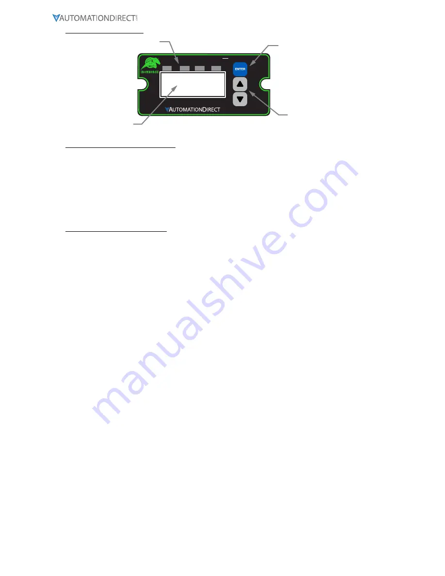
Front Panel Reference
Tach
Parm
Valu
Auto
Alm1
Alm2
Man
Error
---
RIGHT-SET
Display Window
Up & Down Buttons
ENTER (Select) Button
LED Indicators
How to Change an Item’s Value
1) Hold down the Enter button until Item-Selection Mode is entered. The Item Annunciator will light.
2) Using the Up and Down buttons, select the desired Item number to view or edit.
3) Press the Enter button to change the value of the Item. The “Valu” Annunciator will light.
4) Using the Up and Down buttons, change the Item’s value as desired.
5) Press the Enter button to permanently save the changes (Returns to Parameter-Selection Mode).
6) Select Item Zero (“0”) and press the Enter button to return to Running Mode.
Operating the User Interface
Although the GSDA-DP-D speed control unit user interface is very versatile, it is also simple to setup and
operate. With just a few button presses, it allows the user to configure a number of adjustable Parameters.
The LED display has three basic operating modes: Running Mode, Parameter-Selection Mode, and Value
Mode. Parameter and Value modes also have specific visual indicators (LED Annunciators) that allow the
user to immediately determine the current state or mode of the user interface. Note: Parameter-Selection
Mode (and Value Mode) can only be entered if the Program Enable jumper is in the On position.
Running Mode
is the default display of the unit when power is applied. The speed control unit will spend
the majority of its time in this mode. In Running Mode, the display shows the Target or Actual (Tach)
speed value in the user-defined engineering units format for rate, time, or (in Follower mode) percentage
of Master. The control will continuously attempt to drive the motor to the requested Target. In this display
mode, the Up and Down buttons increase or decrease the displayed target value until either the display
minimum or display maximum limit is reached. Depending on the alarm configuration, these buttons may
also serve as an alarm-silence or alarm-reset button. For example, displays for rate, time, and follower
operating modes could be 13.60, 45:30, and 1000, respectively.
Additionally, the speed control unit has an Auto/Manual Annunciator which displays a solid light if the
source of the Target Setting comes from the 4-20mA input (Auto), or a blinking light if the Target Setting
comes from the front panel Target setting (Manual).
Parameter-Selection Mode
can be entered by simply pressing and holding the Enter button down for
about three seconds. Once in Parameter-Selection Mode, the Item Annunciator will illuminate. The
display will indicate the currently selected Item number for editing purposes. Pressing the Up or Down
button will increase or decrease the selected Item number on the display. Although the Parameter numbers
are in numerical order, some numbers are skipped. These numbers represent reserved Parameters that are
not yet implemented and are not displayed.
In addition, Parameter numbers above 999 are actually located on the ModularBus card(s) that are
installed in the host drive. The numbering scheme is the ModularBus slot number (100, 200 or 500) times
10, plus the Parameter number. Once the desired Parameter number is displayed, pressing the Enter button
will change the display to the Value Mode. So, for example, to view/edit Parameter 20 on a ModularBus
card in Slot 200, browse to Parameter number 2020 (200 X 10 + 20). When in Parameter-Selection Mode,
pressing the Enter button with Parameter 0 selected will cause the unit to return to Running Mode. See the
Software Parameters for a list of available Parameters.
Value Mode
is used to modify the value of the selected Parameter. When in Value Mode, the Valu


