background image

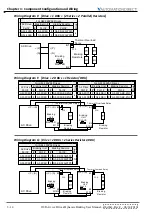
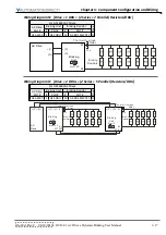
Chapter 3:  Component Configuration and Wiring

3–12

DURA

pUlse

 Drives Dynamic Braking User Manual – 2nd Ed., Rev.C – 06/14/2019

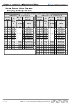
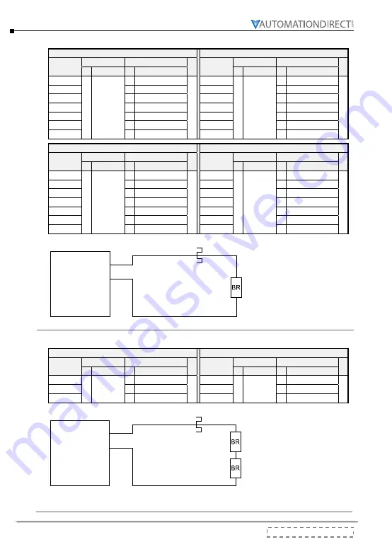
Wiring Diagram A:  [Drive + 1 Resistor]

For GS3 230VAC Drives

For GS3 460VAC Drives

AC Drive 

Part #

Braking Unit

Braking Resistor

Diag.

AC Drive 

Part #

Braking Unit

Braking Resistor

Diag.

#

Part #

#

Part #

#

Part #

#

Part #

GS3-21P0

0

n/a

1

GS-21P0-BR

A

GS3-41P0

0

n/a

1

GS-41P0-BR

A

GS3-22P0

1

GS-22P0-BR

GS3-42P0

1

GS-42P0-BR

GS3-23P0

1

GS-23P0-BR

GS3-43P0

1

GS-43P0-BR

GS3-25P0

1

GS-25P0-BR

GS3-45P0

1

GS-45P0-BR

GS3-27P5

1

GS-27P5-BR

GS3-47P5

1

GS-47P5-BR

GS3-2010

1 GS-2010-BR-ENC

GS3-4010

1

GS-4010-BR

GS3-2015

1 GS-2015-BR-ENC

GS3-4015

1 GS-4015-BR-ENC

For GS4 230VAC Drives

For GS4 460VAC Drives

AC Drive 

Part #

Braking Unit

Braking Resistor

Diag.

AC Drive 

Part #

Braking Unit

Braking Resistor

Diag.

#

Part #

#

Part #

#

Part #

#

Part #

GS4-21P0

0

n/a

1 GS-BR-080W200

A

GS4-41P0

0

n/a

1 GS-BR-080W750

A

GS4-22P0

1 GS-BR-200W091

GS4-42P0

1 GS-BR-200W360

GS4-23P0

1 GS-BR-300W070

GS4-43P0

1 GS-BR-300W250

GS4-25P0

1 GS-BR-400W040

GS4-45P0

1 GS-BR-400W150

GS4-27P5

1 GS-BR-1K0W020

GS4-47P5

1 GS-BR-1K0W075

GS4-2010

1 GS-BR-1K0W020

GS4-4010

1 GS-BR-1K0W075

GS4-2015

1 GS-BR-1K5W013

GS4-4015

1 GS-BR-1K5W043

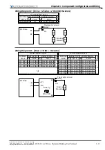
AC Drive 

O.L.

Thermal Overload

Relay

B1

B2

Braking 

Resistor

Wiring Diagram B:  [Drive + 2 Series Resistors]

For GS4 230VAC Drives

For GS4 460VAC Drives

AC Drive 

Part #

Braking Unit

Braking Resistor

Diag.

AC Drive 

Part #

Braking Unit

Braking Resistor

Diag.

#

Part #

#

Part #

#

Part #

#

Part #

GS4-2020

0

n/a

2 GS-BR-1K0W4P3

B

GS4-4020

0

n/a

2 GS-BR-1K0W016

B

GS4-2025

2 GS-BR-1K0W4P3

GS4-4025

2 GS-BR-1K0W016

GS4-2030

2 GS-BR-1K5W3P3

GS4-4030

2 GS-BR-1K5W013

O.L.

Thermal Overload

Relay

B1

B2

Braking

Resistor

AC Drive 

Содержание DURA PULSE GS-2DBU

Страница 1: ...Dynamic Braking User Manual GS DB_UMW...

Страница 2: ...BLANK PAGE...

Страница 3: ...as on line control equipment in hazardous environments requiring fail safe performance such as in the operation of nuclear facilities aircraft navigation or communication systems air traffic control d...

Страница 4: ...des environnements dangereux n cessitant une s curit absolue par exemple l exploitation d installations nucl aires les syst mes de navigation a rienne ou de communication le contr le de la circulatio...

Страница 5: ...drive To avoid personal injury do not remove the cover of the DURApulse Dynamic Brake Unit or the AC drive until the power has been disconnected from the AC drive and all DISCHARGE indicators on the d...

Страница 6: ...W 4 DURApulse Drives Dynamic Braking User Manual 2nd Ed Rev C 06 14 2019 BLANK PAGE...

Страница 7: ...03 2004 Minor changes 1st Ed Rev B 07 2009 GS 2050 BR ENC specifications Second Edition 09 28 2017 User Manual name change previous name GS3 DB M Added GS4 series AC Drives Added 5 GS xDB series Dyna...

Страница 8: ...H 2 DURApulse Drives Dynamic Braking User Manual 2nd Ed Rev C 06 14 2019 User Manual Revision History BLANK PAGE...

Страница 9: ...bols 1 3 Introduction 1 3 Dynamic Braking 1 3 Dynamic Braking Units 1 3 Braking Duty Cycle 1 4 Overload Relay 1 5 Overload Relay Purpose 1 5 Overload Relay Selection Procedure and Example 1 5 Dynamic...

Страница 10: ...ormation 3 2 Overload Relay 3 2 Dynamic Braking Unit Setup 3 3 DBU Jumper and Wiring Terminal Locations 3 3 DBU Voltage Jumper Settings 3 4 DBU Master Slave Jumper Settings 3 5 Dynamic Braking Wiring...

Страница 11: ...l Symbols 1 3 Introduction 1 3 Dynamic Braking 1 3 Dynamic Braking Units 1 3 Braking Duty Cycle 1 4 Overload Relay 1 5 Overload Relay Purpose 1 5 Overload Relay Selection Procedure and Example 1 5 Dyn...

Страница 12: ...al Electrical Manufacturers Association NEMA publishes many different documents that discuss standards for industrial control equipment Global Engineering Documents handles the sale of NEMA documents...

Страница 13: ...onal external braking resistors but higher capacity drives also require optional dynamic braking units installed between the drives and resistors Dynamic Braking Units DURApulse dynamic braking units...

Страница 14: ...ry to allow the dynamic braking unit and braking resistor s sufficient time to dissipate the heat created during dynamic braking If the Duty Cycle is exceeded the braking resistor will not cool suffic...

Страница 15: ...acity Multiple of Current Setting for your selected overload relay The intersection of the Trip Time 10s and the Multiple of Current Setting is 2 6 or 260 for this example response curve The property...

Страница 16: ...2DBU 1 2020 BR ENC 10 2 38 0 10 38 0 14 4 D 25 18 2025 1 2DBU 1 2025 BR ENC 12 2 47 5 8 47 5 18 1 30 22 2030 1 2DBU 1 2030 BR ENC 14 9 55 9 6 8 55 9 21 2 40 30 2040 2 2DBU 2 2040 BR ENC 20 3 38 0 10 3...

Страница 17: ...2W3P9 37 2 145 2 1 180 68 4 J 100 75 2100 4 2DBU 8 1K2W3P9 50 8 190 1 6 240 91 2 K 460V 1 0 7 41P0 0 n a 1 080W750 0 5 1 190 4 3 0 A 2 1 5 42P0 1 200W360 1 2 1 126 7 6 4 6 3 2 2 43P0 1 300W250 1 5 3 1...

Страница 18: ...ARGE Lamp LED Comes ON until DC bus voltage P N drops below 50VDC Comes ON when DC bus voltage DC DC rises above 300VDC Goes OFF when DC bus voltage DC DC drops below 100VDC Braking ACT Lamp LED ON du...

Страница 19: ...0 400 1 GS 43P0 BR 300 250 1 GS 45P0 BR 400 150 1 GS 47P5 BR 500 100 2 GS 4010 BR 1000 75 3 GS 4015 BR ENC 1000 50 enclosed 4 GS 4020 BR ENC 1500 40 7 GS 4025 BR ENC 4800 32 8 GS 4030 BR ENC 4800 27 2...

Страница 20: ...Chapter 1 Overview and Component Specifications 1 10 DURApulse Drives Dynamic Braking User Manual 2nd Ed Rev C 06 14 2019 BLANK PAGE...

Страница 21: ...06 14 2019 DURApulse Drives Dynamic Braking User Manual 2 1 2 2 2 Chapter Chapter Chapter Table of Contents Installation 2 2 General Installation Guidelines 2 2 Minimum Clearances and Air Flow 2 2 Br...

Страница 22: ...nit vertically and do not restrict the air flow to the heat sink fins Warning The Dynamic Brake Unit and Braking Resistors generate large amounts of heat which may damage the braking unit resistors or...

Страница 23: ...n Wall Wall Wall Wall Braking Resistor Wall Wall Floor Ceiling 150mm 6in Horizontal Mounting Vertical Mounting Braking Resistor 150mm 6in Braking Resistor 150mm 6in 150mm 6in Braking Resistor 150mm 6i...

Страница 24: ...ion and Dimensions 2 4 DURApulse Drives Dynamic Braking User Manual 2nd Ed Rev C 06 14 2019 Braking Unit Dimensions A DBU 100hp GS 1DBU GS 2DBU GS 3DBU GS 4DBU Dimensions mm in B DBU 100hp GS 5DBU GS...

Страница 25: ...C 4 GS 4015 BR ENC 4 GS BR 400W040 10 GS BR 1K2W015 11 GS 2015 BR ENC 5 GS 4020 BR ENC 7 GS BR 400W150 10 GS BR 1K5W3P3 11 GS 2020 BR ENC 5 GS 4025 BR ENC 8 GS BR 1K5W012 11 GS 2025 BR ENC 6 GS 4030 B...

Страница 26: ...m in GS 27P5 BR GS 47P5 BR L1 L2 H D W 335 13 19 320 12 60 30 1 18 5 3 0 21 60 2 36 3 GS 4010 BR Dimensions mm in GS 4010 BR L1 L2 H D W 400 15 75 385 15 16 50 1 97 5 3 0 21 100 3 94 4 GS 2010 BR ENC...

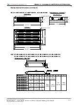
Страница 27: ...imensions in mm FRONT VIEW TOP VIEW LEFT SIDE VIEW THERMOSTAT N C 4 7 16 11 11 DIA 4 1 2 INCH CONDUIT K O 5 127 0 10 254 0 5 127 0 19 482 6 7 5 190 5 10 254 0 17 5 444 5 19 482 6 6 GS 2025 BR ENC GS 2...

Страница 28: ...EW TOP VIEW LEFT SIDE VIEW THERMOSTAT N C 4 11 11 7 16 DIA 4 1 2 INCH CONDUIT K O 5 127 0 13 330 2 5 127 0 12 304 8 10 5 266 7 13 330 2 10 5 266 7 12 304 8 8 GS 4025 BR ENC GS 4030 BR ENC GS 4040 BR E...

Страница 29: ...127 0 16 406 4 5 127 0 26 5 673 1 16 406 4 13 5 342 9 25 635 0 26 5 673 1 10 GS BR 080W200 GS BR 080W750 GS BR 200W091 GS BR 200W360 GS BR 300W070 GS BR 300W250 GS BR 400W040 GS BR 400W150 Dimensions...

Страница 30: ...es Dynamic Braking User Manual 2nd Ed Rev C 06 14 2019 Braking Resistor Dimensions continued 11 GS BR 1K0W4P3 GS BR 1K0W5P1 GS BR 1K0W016 GS BR 1K0W020 GS BR 1K0W075 GS BR 1K2W3P9 GS BR 1K2W015 GS BR...

Страница 31: ...cal Information 3 2 Overload Relay 3 2 Dynamic Braking Unit Setup 3 3 DBU Jumper and Wiring Terminal Locations 3 3 DBU Voltage Jumper Settings 3 4 DBU Master Slave Jumper Settings 3 5 Dynamic Braking...

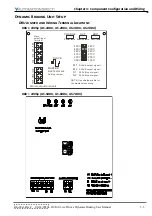
Страница 32: ...it will be activated when the temperature of the braking unit heat sink exceeds 203 F 95 C for DBUs 100hp or 176 F 80 C for DBUs 100hp This condition can be caused by the ambient temperature surroundi...

Страница 33: ...S 3DBU GS 4DBU 480V 460V 440V 415V 400V 380V 240V 230V 220V 210V 200V 190V MASTER SLAVE Setting Jumper M1 M2 S1 S2 SLAVE output signal SLAVE output signal SLAVE input signal SLAVE input signal NOTE Us...

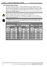
Страница 34: ...dynamic braking when the power supply voltage rises above 380VAC set the voltage selection jumper to the 415VAC position For DURApulse AC drives set the Over Voltage Stall Prevention parameter as clos...

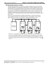
Страница 35: ...llow rapid deceleration of the motor Typical one line wiring diagram for multiple parallel DURApulse dynamic braking units The first DBU has the jumper set to MASTER while the remaining DBUs are set t...

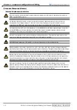
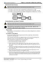
Страница 36: ...or larger than leads P and N or DC and DC DO NOT wire terminals N or DC to the neutral point of the power system During braking the wires connected to P N DC DC B1 and B2 generate powerful electromagn...

Страница 37: ...pment where the acceptability is determined by Underwriters Laboratories Inc This component controller has been judged on the basis of the required spacings in the Standard for Power Conversion Equipm...

Страница 38: ...2 AWG 3 5 5 5 mm2 M4 15 6 in lb 18 kg cm Slave Circuit Output M1 M2 18 20 AWG 0 8 0 5 mm2 with shielded wires M2 3 in lb 4 kg cm Input S1 S2 Fault Circuit RA RB RC 18 20 AWG 0 8 0 5 mm2 M2 3 in lb 4 k...

Страница 39: ...the braking resistor and are the preferred method of protection when available Orient the braking resistors such that the thermostat is above the resistors in the enclosure as this will ensure that th...

Страница 40: ...a 1 21P0 BR A 1 0 7 41P0 0 n a 1 41P0 BR A 2 1 5 22P0 1 22P0 BR 2 1 5 42P0 1 42P0 BR 3 2 2 23P0 1 23P0 BR 3 2 2 43P0 1 43P0 BR 5 3 7 25P0 1 25P0 BR 5 3 7 45P0 1 45P0 BR 7 5 5 5 27P5 1 27P5 BR 7 5 5 5...

Страница 41: ...2 2 43P0 1 300W250 5 3 7 25P0 1 400W040 5 3 7 45P0 1 400W150 7 5 5 5 27P5 1 1K0W020 7 5 5 5 47P5 1 1K0W075 10 7 5 2010 1 1K0W020 10 7 5 4010 1 1K0W075 15 11 2015 1 1K5W013 15 11 4015 1 1K5W043 20 15 2...

Страница 42: ...istor Diag AC Drive Part Braking Unit Braking Resistor Diag Part Part Part Part GS4 21P0 0 n a 1 GS BR 080W200 A GS4 41P0 0 n a 1 GS BR 080W750 A GS4 22P0 1 GS BR 200W091 GS4 42P0 1 GS BR 200W360 GS4...

Страница 43: ...r For GS3 230VAC Drives For GS3 460VAC Drives AC Drive Part Braking Unit Braking Resistor Diag AC Drive Part Braking Unit Braking Resistor Diag Part Part Part Part GS3 2020 1 GS 2DBU 1 GS 2020 BR ENC...

Страница 44: ...Unit Braking Resistor Diag Part Part Part Part GS3 2040 2 GS 2DBU 2 GS 2040 BR ENC F GS3 4075 2 GS 4DBU 2 GS 4075 BR ENC F GS3 2050 2 GS 2DBU 2 GS 2050 BR ENC GS3 4100 2 GS 4DBU 2 GS 4100 BR ENC O L B...

Страница 45: ...ives AC Drive Part Braking Unit Braking Resistor Diag Part Part GS4 4100 2 GS 4DBU 8 GS BR 1K2W015 I GS4 4125 2 GS 4DBU 8 GS BR 1K5W013 O L B1 B2 Braking Unit SLAVE S1 S2 O L Braking Resistor B1 B2 Br...

Страница 46: ...Thermal Overload Relay Thermal Overload Relay Thermal Overload Relay Braking Resistors Braking Resistors Braking Resistors Wiring Diagram L Drive 1 DBU 2 Series 5 Parallel Resistors DBU For GS4 460VA...

Страница 47: ...GS 7DBU 14 GS BR 1K5W012 N Braking Unit P N P N MASTER O L B1 B2 Thermal Overload Relay Braking Resistors AC Drive Wiring Diagram O Drive 2 DBUs 2 Series 5 Parallel Resistors DBU For GS4 460VAC Drive...

Страница 48: ...Chapter 3 Component Configuration and Wiring 3 18 DURApulse Drives Dynamic Braking User Manual 2nd Ed Rev C 06 14 2019 BLANK PAGE...

Страница 49: ...2nd Ed Rev C 06 14 2019 DURApulse Drives Dynamic Braking User Manual BLANK PAGE...

Страница 50: ...DURApulse Drives Dynamic Braking User Manual 2nd Ed Rev C 06 14 2019...

Отзывы: