Chapter 3: Component Configuration and Wiring
DURA
pUlse
Drives Dynamic Braking User Manual
3–13
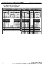
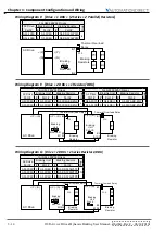
Wiring Diagram C: [Drive + (2 2 Parallel) Resistors]
For GS4 460VAC Drives
AC Drive
Part #
Braking Unit
Braking Resistor
Diag.
#
Part #
#
Part #
GS4-4040 0
n/a
4 GS-BR-1K0W016 C
O.L.
Thermal Overload
Relay
B1
B2
AC Drive
Braking
Resistor
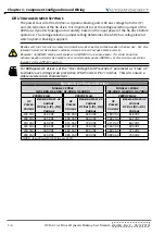
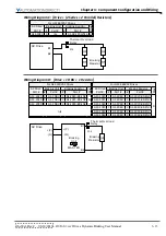
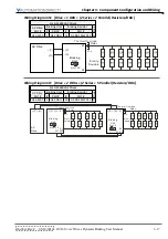
Wiring Diagram D: [Drive + 1 DBU + 1 Resistor]
For GS3 230VAC Drives
For GS3 460VAC Drives
AC Drive
Part #
Braking Unit
Braking Resistor
Diag.
AC Drive
Part #
Braking Unit
Braking Resistor
Diag.
#
Part #
#
Part #
#
Part #
#
Part #
GS3-2020 1 GS-2DBU 1 GS-2020-BR-ENC
D
GS3-4020 1 GS-4DBU 1 GS-4020-BR-ENC
D
GS3-2025 1 GS-2DBU 1 GS-2025-BR-ENC
GS3-4025 1 GS-4DBU 1 GS-4025-BR-ENC
GS3-2030 1 GS-2DBU 1 GS-2030-BR-ENC
GS3-4030 1 GS-4DBU 1 GS-4030-BR-ENC
n/a
GS3-4040 1 GS-4DBU 1 GS-4040-BR-ENC
GS3-4050 1 GS-4DBU 1 GS-4050-BR-ENC
GS3-4060 1 GS-4DBU 1 GS-4060-BR-ENC
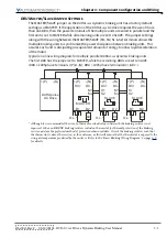
O.L.
B1
B2
Braking
Unit
Thermal Overload
Relay
+ P
- N
( )
( )
Braking
Resistor
+ P
- N
( )
( )
MASTER
AC Drive
Содержание DURA PULSE GS-2DBU
Страница 1: ...Dynamic Braking User Manual GS DB_UMW...
Страница 2: ...BLANK PAGE...
Страница 6: ...W 4 DURApulse Drives Dynamic Braking User Manual 2nd Ed Rev C 06 14 2019 BLANK PAGE...
Страница 49: ...2nd Ed Rev C 06 14 2019 DURApulse Drives Dynamic Braking User Manual BLANK PAGE...
Страница 50: ...DURApulse Drives Dynamic Braking User Manual 2nd Ed Rev C 06 14 2019...

