background image

Revised 8/14/02 • U551

6

© 2002 Automated Logic Corporation

2. Check the Unet communication wiring for 

shorts, grounds, or opens.

3. Connect the Unet communication wires to 

the Unet Port (see Figure 1 on page 3). 

Replace the module's power jumper. You 
must transfer memory to the UNI before the 
U551 is recognized.

Communicating Through the 

LogiStat Port

You can connect your workstation to the Unet 
and the ARC156 or Legacy CMnet network 
segment using a LogiStat sensor. While 
connected, the UNI does not allow a restart 
(zap), a memory transfer, or any other action 
that would break the passthrough 
connection.

The LogiStat Port connection does not apply 
in WebCTRL.

To communicate through the LogiStat port, 
the U551 must:

• be connected to a UNI on an ARC156 

network segment

• use the appropriate module driver

For SuperVision systems, use a version 
6.01d or later of the U1M, U3M, U5M, or 
UNM module driver

Communication speed is fixed at 1200 baud.

1. Connect the computer’s serial port to the 

EIA-232 port of the APT using a standard 
straight-through cable.

2. Set the APT’s Mode Select switch to TTL 

(see Figure 6 on page 7).

If you are using a LogiStat Plus without 
supplemental power to the APT, make 
sure the LED on the Logistat Plus is on 
indicating that it can provide power to the 
APT. If the LED is not on, you can provide 
power to the APT using the Supplemental 
Power +5V dc connection (see Figure 6 on 
page 7
) and the special power cable to a 
laptop keyboard jack, or an external 
supply, such as a 5V dc transformer.

3. Define the connection type.

In SuperVision v3.0, define the connection 
as Access Port.

In SuperVision v2.6, define the connection 
as Direct Connect.

4. Set the baud rate at 1200 bps.

5. Attach the LogiStat Adaptor cable (ALC 

part number 235022) to the APT cable. 
Use this assembly to connect the APT’s 
Access Port to the LogiStat’s LogiPort.

While connected, the LogiStat Pro 
displays “LP” indicating that the LogiStat 
Pro will not respond to input from the 
keypad.

NOTE

When the LogiStat Adaptor cable 

is inserted into the LogiPort, the U551 can 
no longer read the LogiStat inputs. The 
U551 continues to use the last valid 
temperature and setpoint adjust readings 
obtained before the cable was inserted 
into the LogiPort. If the occupancy 
override timer was active when the 
connection was made, it continues to 
count down, but no new values can be 
obtained for these inputs until the 
LogiStat Adaptor cable is removed. See 
the 

Eikon for WebCTRL Microblock 

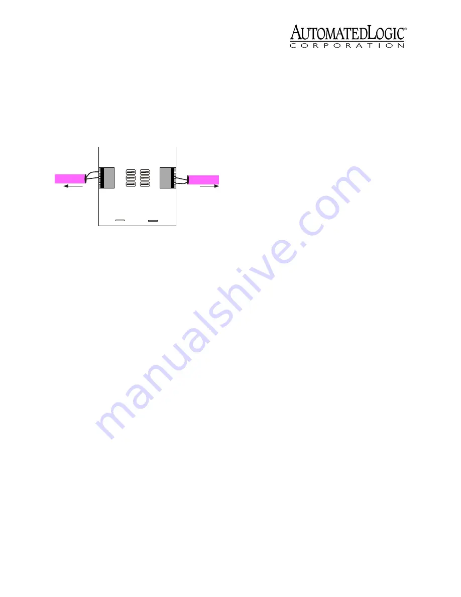
 Figure 5. Using the PROT485 on the Unet

U n f u s e d :

U s e f o r in s id e

w i r i n g

E A R T H G R O U N D

PROT485

E ART H GRO U ND

RE V 0

Au tomated Logic, C orp

S h a r e d c o n n e c t i o n :
F u s e d o r u n f u s e d

-

+

+

-

To UNI

To U modules

Содержание U551

Страница 1: ...ed trademark of ASHRAE All other brand and product names are trademarked by their respective companies Technical Instructions U55 1 Using the U551 2 Specifications 2 Job Start Up 3 Job Start Up for WebCTRL 3 Job Start Up for SuperVision 3 Start Up Checklist 4 Mounting 4 Addressing 4 Power Wiring 4 Communications Wiring 5 Communicating Through the LogiStat Port 6 Input Wiring 7 Using the LogiStat 7...

Страница 2: ...kon User s Guide for more information NOTE To operate this module based on a schedule the UNI must be networked with a gateway module U551 modules have been designed to meet low end high volume terminal control applications As a result time critical applications such as short time delays and trend intervals of less than one minute should not be used with these modules ALC recommends that all time ...

Страница 3: ...need these items to properly start up and support U cards UNI 16 with the U1M module driver UNI 30 with the U3M module driver UNI 32 with the UNM module driver or UNI 59 with the U5M module driver Eikon 3 0a or later Figure 1 U551 Layout and Dimensions Ones Tens Gnd Temp Sw LS5v L o g i S t a t Tx Enclosed Energy 88FO E143900 TYPE 000553 Management Equipment R Run n c Gnd AO 1 DO 5 DO 4 DO 3 DO 2 ...

Страница 4: ...fied This number is shown on the UNI Properties page in WebCTRL or on the UNI Status page in SuperVision Power Wiring The Unet follows the same specifications as a legacy CMnet Refer to the Technical Handbook for details on legacy CMnets Also refer to the Technical Handbook for detailed information on daisy chain star and hybrid wiring configurations There is a special wire available that contains...

Страница 5: ...is unshielded Shielded cable is not required for the Unet In most circumstances you should have a PROT485 within 250 feet of any U line module on the Unet for surge protection However depending on the frequency of electrical surges in your area the 250 foot recommendation may vary For example if you have frequent electrical storms in your area you may want to use more PROT485s if you have few elec...

Страница 6: ...hat it can provide power to the APT If the LED is not on you can provide power to the APT using the Supplemental Power 5V dc connection see Figure 6 on page 7 and the special power cable to a laptop keyboard jack or an external supply such as a 5V dc transformer 3 Define the connection type In SuperVision v3 0 define the connection as Access Port In SuperVision v2 6 define the connection as Direct...

Страница 7: ...behind the input port You must remove the cover to access the pull up jumpers The output impedance of a 0 to 5VDC source must not exceed 10kohms The input impedance of the U551 is approximately 1Mohm Dry Contact A 5VDC wetting voltage is used to detect contact position This results in a 0 5mA maximum sense current when the contacts are closed No pulse accumulation inputs are allowed in U551 FBs ex...

Страница 8: ...le Be sure the U551 s power is off before wiring any inputs or outputs Connect the output wiring to the screw terminals on the module To verify each output s operation lock the output to a known condition on the Function Block s Properties page in WebCTRL or the Parameter page in SuperVision then make sure the equipment operates as specified Using Flow Sensors The U551 controls air flow in the zon...

Страница 9: ...ge in WebCTRL or Parameter page in SuperVision Refer to the Eikon for WebCTRL Microblock Reference Guide or the Eikon Microblock Reference Guide for more information NOTE When installing the UDF be sure to permanently remove the W4 jumper as shown in Figure 12 prior to performing test and balance Writing GFBs for the U55 1 Depending on whether you are using a WebCTRL or a SuperVision system you mu...

Страница 10: ...ence Guide You do not need to use BACnet microblocks when writing the GFB unless you have a BACview Keypad Display connected to the UNI You must then use BACnet point microblocks to access U551 points through the keypad Point Identifiers A point can be identified in WebCTRL by its point number and point type in SuperVision a point is identified by its channel number On both systems expander number...

Страница 11: ...gital 21 IN 2 Thermistor 32 17 to 213 F 27 to 100 6 C 0 00 0 00 15 88 15 69 Volts 32 0 to 5V Digital 22 Sw Thermistor A3 17 to 213 F 27 to 100 6 C 0 00 0 00 15 88 15 69 Digital B3 LogiStat Temp Thermistor A1 or A2 45 to 100 F 7 22 to 37 8 C 0 00 0 00 15 88 15 69 LogiStat Thermistor 33 17 to 213 F 27 to 100 6 C 0 00 0 00 15 88 15 69 IN 3 or UDF 2 Volts 33 0 to 5V Digital 23 UDF 2 Flow CFM Flow inpu...

Отзывы: