Revised 8/14/02 • U551
7
© 2002 Automated Logic Corporation
Reference Guide
or the
Eikon Microblock
Reference Guide
for more information
about the LogiStat microblock.
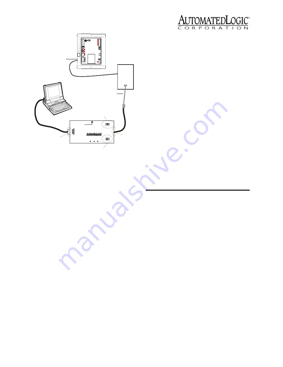
6. Disconnect the LogiStat Adaptor cable
from the LogiStat’s LogiPort when
finished to allow the U551 to read inputs
from the LogiStat.
Input Wiring
The U551 inputs support the types of signals
listed below. The LogiStat, LogiStat Plus, and
LogiStat Pro sensors are supported through
the module’s LogiStat port. The U551
provides five inputs: two on the LogiStat port
and three analog inputs. Refer to Table 1 for
information about wire length, gauge, and
shielding. Make sure the U551’s power is off
before wiring any inputs or outputs.
NOTE
If you are using both flow sensors on
a UDF, disable the U551’s IN-3 input by
removing its jumper. Disabling the IN-3
allows a second flow sensor input (Flow #2)
on the UDF to be read through the flow
sensor on the U551.
• Thermistor: Precon type 2 (10kohm at
77°F). Input voltages should range
between 0.489V and 3.825V for
thermistors.
• 0 to 5VDC: When using 0 to 5VDC
signals, remove the pull up jumpers of
the U551. The pull up jumpers are
located behind the input port. You must
remove the cover to access the pull up
jumpers. The output impedance of a 0
to 5VDC source must not exceed
10kohms. The input impedance of the
U551 is approximately 1Mohm.
• Dry Contact: A 5VDC wetting voltage is
used to detect contact position. This
results in a 0.5mA maximum sense
current when the contacts are closed.
No pulse accumulation inputs are allowed in
U551 FBs, except for the override button on
the LogiStat.
Using the LogiStat
Use Figure 7 and Figure 8 on page 8 to wire a
LogiStat, LogiStat Plus, or LogiStat Pro to the
U551.
Automated Logic Corporation recommends a
specific wire to connect the U551 to the
LogiStat. This 22AWG solid copper wire is
available from Magnum Cable Corporation,
product number A3LOGISTAT.
Figure 6. Using the LogiPort
Gnd
24 Va c
G n d
T e m p
S w
LS 5v
U n e t +
U n e t -
U - c o m
O n
O f f
BACnet
U551
9
Rx
6 1
2- Tx out
3- Rx in
5- Gnd
1,6,8- +10Vor floating
Tx
+5V
A P T
5
Exec. 4relay
Isolate Network
ModeSelect
TTL
485
ACCESS
PORT
Supplemental
Power
+5V dc
LogiStat
Port
LogiStat Adaptor Cable
Access
Port
Mode Select
Switch
EIA-232
Port
Exec 4 Relay
Switch
LogiStat
Table 1. Input Wiring Restrictions
Input
Maximum
Length
Minimum
Gauge
Shielding
Universal
50 feet
15 meters
24AWG
shielded and
grounded to
module’s “-”
or Gnd
terminal
LogiStat
Sensors
100 feet
30 meters
22AWG
unshielded


