Autojack Mig Master MIG100 Скачать руководство пользователя страница 13


OPERATION 


Operation 

Before any work on the machine itself, remove 
the mains plug from outlet. 

Setting  

Since the welding set must be set to suit the 
specific application, we recommend that the 
settings be made on the basis of a test weld.  

 
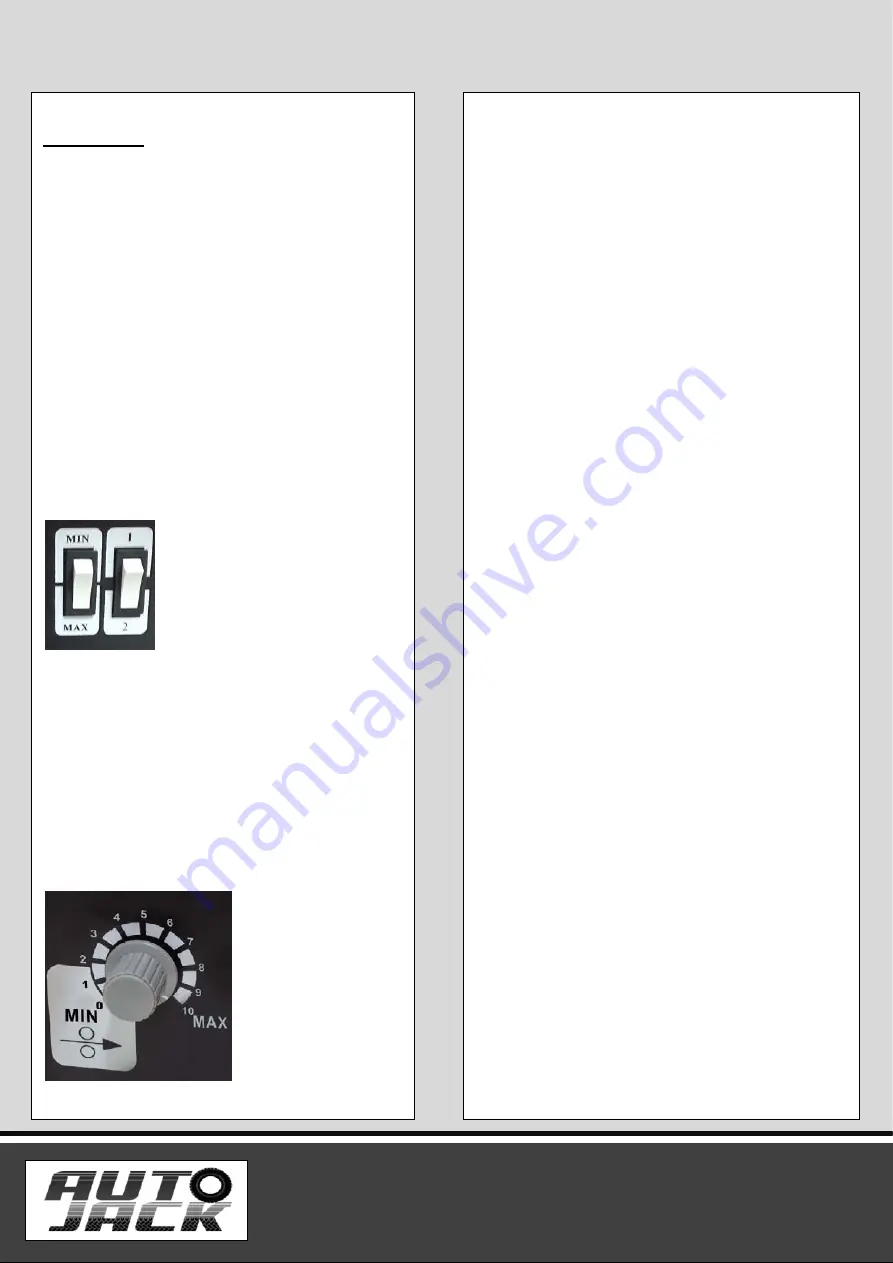
 Setting the welding current  

-The welding current can be set to 2 different 
levels using the welding current adjustment 
switch (6). The required welding current 
depends on the material thickness, the required 
penetration depth and the welding wire 
diameter.  


Setting the wire feed speed  

-The wire feed speed is automatically adjusted to 
the current setting. The final wire feed speed 
setting can be made on the welding wire speed 
controller (5). It is advisable to start with the 
medium setting and to re-adjust the speed as 
necessary. The required quantity of wire 
depends on the material thickness, the 
penetration depth, the welding wire diameter 
and also the size of the gap to be bridged 
between the workpieces you wish to weld.  


Electrical connection  

-Before you connect the equipment to the mains 
supply make sure that the data on the rating plate 
are identical to the mains data.  
 
-The equipment may only be operated from 
properly earthed and fused shock-proof sockets.  
 

Connecting the earth terminal  

-Connect the welding set’s earth terminal (8) in 
the immediate vicinity of the welding position if 
possible. Ensure that the contact point is bare 
metal.  
 

 Welding  

-When all the electrical connections for the power 
supply and welding current circuit have been 
made, you can proceed as follows:  
 
-The workpieces for welding must be clear of 
paint, metallic coatings, dirt, rust, grease and 
moisture in the area where they are to be welded. 
  
-Set the welding current and wire feed 
 
-Hold the welding screen (13) in front of your face 
and move the welding nozzle to the point on the 
workpiece where you wish to complete the weld. 
Now press the torch switch (14).  
 
-When the arc is burning, the welding set will feed 
wire into the weld pool. When the weld nugget is 
large enough, move the torch slowly along the 
required edge. Move it to and fro if necessary to 
enlarge the weld pool a little.  
 
-Find the ideal setting of the welding current and 
wire feed speed by carrying out a test weld. Ideally 
an even welding noise will be audible. The 
penetration depth should be as deep as possible, 
but the weld pool must not be allowed to fall 
through the workpiece.  


MIG100/MIG130                          11

Содержание Mig Master MIG100

Страница 1: ...MIG100 MIG130 Mig Master MIG100 MIG130 ORIGINAL INSTRUCTIONS SAFETY AND OPERATING MANUAL...

Страница 2: ...de you with all information necessary for using the product safely and to ensure its long service life Closely observe all safety information in these instructions General Power Tool Safety Warnings 0...

Страница 3: ...carrying pulling or unplugging the power tool Keep cord away from heat oil sharp edges or moving parts Damaged or entangled cords increase the risk of electric shock e When operating a power tool outd...

Страница 4: ...ate the power tool Power tools are dangerous in the hands of untrained users e Maintain power tools Check for misalignment or binding of moving parts breakage of parts and any other condition that may...

Страница 5: ...on both hands for welding These offer protection from electric shocks idling voltage in the welding circuit harmful radiation Heat and UV radiation and from glowing metal and slag spatter f Wear firm...

Страница 6: ...fuse may result in the cable burning and fire damage to the building 8 Additional Safety Instructions for Constricted and wet areas When working in constricted wet or hot areas use insulating supports...

Страница 7: ...em for example by coating them with a suitable paint Do not store or use the equipment in wet conditions or in the rain Use the equipment only indoors 11 Using an Extension Cable a If an extension cab...

Страница 8: ...ear defenders The impact of noise can cause damage to hearing Amperes 7 5M 15M 25M 30M 45M 60M 0 2 0 6 6 6 6 6 6 2 1 3 4 6 6 6 6 6 6 3 5 5 0 6 6 6 6 10 15 5 1 7 1 10 10 10 10 15 15 7 1 12 0 15 15 15...

Страница 9: ...tended Use The flux cored welding set is designed for self shielding flux cored welding using suitable wire The additional application of gas is not required The equipment is to be used only for its p...

Страница 10: ...p 3 Housing cover 4 ON OFF switch 5 Welding wire speed controller 6 Switch for welding current adjustment 7 Mains plug 8 Earth terminal 9 Hose package 10 Welding nozzle 11 Torch 12 Wire brush 13 Weldi...

Страница 11: ...s match each other 2 Wire spool capacity Wire spools with a maximum weight of 0 45 kg can be fitted in the welding set 3 Inserting the wire spool 1 Unlock the housing cover by turning the fastening sc...

Страница 12: ...duce a straight cut with no shoulders warping or dirt Deburr the end of the welding wire 8 Push the welding wire through the guide tube C between the pressure and feed rollers G into the hose package...

Страница 13: ...entical to the mains data The equipment may only be operated from properly earthed and fused shock proof sockets Connecting the earth terminal Connect the welding set s earth terminal 8 in the immedia...

Страница 14: ...ce Always pull out the mains power plug before starting any cleaning work Cleaning Keep all safety devices air vents and the motor housing free of dirt and dust as far as possible Wipe the equipment w...

Страница 15: ...ction misuse alteration or repair of the product without approval 1 2 5 The product has been used in a domestic environment only 1 2 6 The fault does not relate to consumable items such as blades bear...

Страница 16: ...ote that it is essential that the letter of claim reaches Autojack on the last day of this guarantee at the latest Late claims will not be considered 3 Limitation of Liability 3 1 We only supply produ...

Страница 17: ...ter MIG100 MIG130 Is in compliance with the regulations included in the Directives 2006 42 EC EC DECLARATION OF CONFORMITY Certificate for EC type examination delivered by AV Technology Ltd Unit 2 Eas...

Страница 18: ...e feed 23 Knob 7 Screw 24 Fan 8 Wire spool holder 25 Overheating indicator light 9 Screw 26 Power switch 10 Spacer 27 Adjustment switch 11 Nut 28 Water joint 12 Rivet 29 Earth clamp 13 Guard ring of t...

Страница 19: ...Parts Diagram MIG100 MIG130 17...

Отзывы: