© Austria Email AG
17
id.: 17-14-35-1251-08 | 02.2016
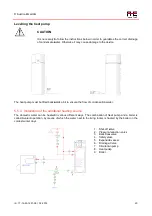
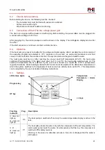
1. Shut-off valve
2. Pressure reduction valve
3. Back-flow valve
4. Safety valve
5. Expansion vessel
6. Drainage Valve
7. Circulation pump
8. Heat pump
Expansion vessel dimensioning:
Safety valve pressure setting [bar]
6
10
Pressure in system [bar]
3.0
3.5
4.0
3.0
3.5
4.0
Storage volume [L]
Expansion vessel volume [L]
300
15
19
26
9
10
10
5.5.2 Air duct connection
The heat pump with air duct has several advantages over the standard compact version and also over the
design with a separate evaporator:
•
The heat pump can be set up in any room which is big enough to accommodate it.
•
The thermal pump enables the ventilation of a selected room
•
The heat pump enables the drawing off of the ambient air and also enables the supply of fresh air
from the surroundings.
•
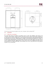
When selecting the room, take into account the diameter and height of the heat pump. There must
be sufficient space above for the pipe channel connections. The minimum distance to the walls must
be 0.5 m.
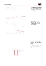
The air piping system should be designed in such a way that, on its way, the air does not change the
direction of its flow if possible. The pipe length between the intake connection and the outlet connection
should not exceed 10 m. If the flow direction changes more often, that must be regarded as additional air
resistance and the pipe length should be shortened accordingly. A 90° bend therefore means a pipe channel
shorter by 0.5 m. Closure elements (gates, filters, ventilation valves) in the air ventilation system must be
taken into account in the same way. A drop in pressure in the pipe channel which is too high reduces the air
flow. If the air temperature is below +10°C, this can cause the slow freezing of the evaporator and thus
poorer ventilation, which is something which is difficult to notice.
REMARK
It is necessary to install at least a 90° elbow pipe in order to avoid a mixture of air
between the suctioning air channel and the blowing out air channel.


