D201RH / RHS / RHG / RHGS
14
Special
Safety
Messages
(fi
g.
1)
(fi
g.
2)
General comments
AUSA manufactures its dumpers in accordance with the intrinsic protection
requirements, as established by current legislation in the countries of the European
Economic Community, regarding the dangers of any nature which may put health or
life at risk, whenever the machinery is in use and maintained in accordance with these
guidelines. Any danger resulting from improper use, not complying with these provisions
or others which are specifically provided with the machinery, shall be the responsibility of
the user and not of AUSA.
This section provides instructions on the use of the dumper, in accordance with that
established by the Directive for Safety of Machinery 2006/42/EC.
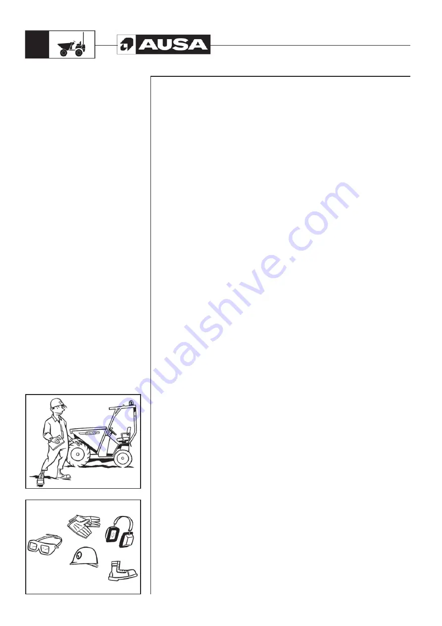
Before using the dumper which is initially unfamiliar, you should read the Manual closely
and resolve any doubts with a supervisor
(fig. 1)
.
The dumper must only be used by authorized and correctly trained personnel.
Operator clothing
Request the personal protective equipment required to carry out the work in safety, for
example: helmet, protective earmuffs, outwears clothing, reflective equipment, safety
goggles, etc.
(fig. 2)
.
The wearing of bracelets, chains, loose ropes, long hair which is not tied up, etc., is
not recommended due to the risk of catching these in controls, rotating components,
edges, etc.
Dumper description
A dumper is an engine-driven dumper used to carry loads with the help of special
attachments designed for the intended work (bucket and, depending on the version,
self-loading shovel). The dumper can tip the bucket in order to unload it. It consists of a
resistant chassis resting upon two axles. The front axle is the drive axle and the rear axle
the steering axle, although versions exist in which both axles are drive axles.
The front of the dumper is equipped with the bucket and, depending on the version, the
self-loading shovel. The unit formed by both is designed to lift and tilt the load forwards
and backwards, making handling easier.
Rudiments of static equilibrium
So that the dumper is able to handle loads in a stable and safe manner, certain equilibrium
conditions must exist and be maintained between the load and the machinery. For
this reason the dumper has been fitted with counterweights. These are designed to
compensate for the weight of the load being carried, as long as the centre of gravity
of the load and the dumper are within certain established limits. See the DUMPER
IDENTIFICATION PLATE in order to verify the load capacity and the load centre of gravity
permitted.
Rudiments of dynamic equilibrium
While the dumper is moving, and as it gains speed, the equilibrium conditions of the
load-dumper unit are modified as the centre of gravity shifts. This is accentuated on
lifting loads, turning, braking, etc. Under these conditions, a maximum of concentration
is required so that the centre of gravity of the load is kept within the established limits.
Dumper equilibrium
The dumper counterweight counter acts imbalance of the weight even when unloading.
The centre of gravity is maintained low and close to the rear of the dumper. When the
load is collected, the imbalance is corrected and the centre of gravity shifts forward. If
the load is within the correct limits then the correct equilibrium is maintained. As the load
is lifted, the centre of gravity also rises, shifting upwards. At the moment that the centre
of gravity shifts beyond the dumper, the equilibrium is lost and the dumper becomes
unstable. Therefore, the dumper should not move while the bucket is raised.
Содержание D 201 RH
Страница 1: ...D 201 RH D 201 RHS D 201 RHG D 201 RHGS OPERATOR S MANUAL ENGLISH Original Manual ...
Страница 2: ......
Страница 3: ...D 201 RH D 201 RHS D 201 RHG D 201 RHGS Original Manual Above chassis number 62439 ...
Страница 4: ......
Страница 66: ...D201RH RHS RHG RHGS 64 Electric Diagram H1 ...
Страница 67: ...D201RH RHS RHG RHGS 65 Electric Diagram H2 ...
Страница 68: ...D201RH RHS RHG RHGS 66 Electric Diagram H3 ...
Страница 69: ...D201RH RHS RHG RHGS 67 Electric Diagram H4 ...
Страница 72: ...D201RH RHS RHG RHGS 70 D 201 RH hydraulic diagram ...
Страница 73: ...D201RH RHS RHG RHGS 71 D 201 RHS hydraulic diagram ...
Страница 74: ...D201RH RHS RHG RHGS 72 D 201 RHG hydraulic diagram ...
Страница 75: ...D201RH RHS RHG RHGS 73 D 201 RHGS hydraulic diagram ...
Страница 76: ...D201RH RHS RHG RHGS 74 Transmission hydraulic diagram ...
Страница 78: ......
Страница 79: ......
Страница 80: ......


