


RTX-24EM
User guide
The technical characteristics can change without notice. AUR°EL S.p.A doesn’t assume the responsibility to the damages caused by an improper use of the device.
AUR°EL S.p.A.
Via Foro dei Tigli, 4 - 47015 Modigliana (FC) – ITALY 12/11/2019 - Rev. B
Tel.: +390546941124 – Fax: +390546941660 Page 13
http://www.aurel.it
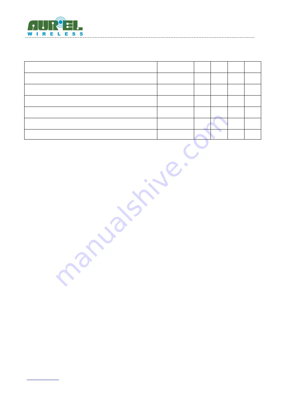
Parameter
Symbol
Min
Typ
Max
Unit
Power Down
Standby mode (crystal oscillator OFF)
t
PD-STBY
100
µs
Standby mode (crystal OFF)
Standby mode Crystal oscillator ON
t
STBY-OSC_ON
900
µs
RAM2 Init
t
RAM2_INIT
200
µs
VCO Auto calibration
t
VCO_CAL
340
500
µs
PTAT current Auto calibration
t
PTAT_CAL
150
µs
Standby mode crystal oscillator ON
TX/RX mode
t
STBY-RF
0.8
1
ms
Table 6: Timing characteristics (Vcc = 3V)
8.
Digital interface
The RTX-24EM can be controlled with a 4-wire serial peripheral interface (SPI). The four wires are:
SS
Slave Select
SCK
Serial Clock
MOSI
Serial data in to RTX-24EM
MISO
Serial data out of RTX-24EM
The RTX-24EM has a programmable interrupt pin (IRQ).
All internal enables signals and parameters of the RTX-24EM are mapped in a small 16x12 bits memory
called RAM2. RAM2 can directly be accessed through SPI and no crystal clock is required.
8.1
SPI operations
The SPI interface is used to read from and to write all the register of the EM9209 embedded on the RTX-
24EM module.
SPI operations allow various accesses:
•
Memories write and read actions
•
EM9209 internal microcontroller commands
•
Loading of subroutines in RAM1
A SPI transaction is defined as all of the activity on SCK, MOSI and MISO that occurs between one rising
edge of SS and its next falling edge. All the data shall be sent starting with the MSB first.
Not all the commands are encoded on a number of bits multiple of 8. Additional clocks can be sent after
the command with no impact on the command decoding. Thus, the EM9209 can be accessed without


