24
Assembly Instruction
KSA - T
WIN
S12 24V DC
I
NSTALLATION
STEP
11:
E
LECTRIC
CONNECTION
07
I
NSTALLATION
STEP
11:
E
LECTRIC
CONNETCTION
M-COM (Main control unit)
Order number:
Application:
Rated voltage:
Current consumption:
Drive type:
Protection class:
Ambient temperature:
Dimensions:
Connecting wires:
524177
Main control unit for the automatic
confi guration and monitoring of max. 2
opening / 2 locking drives type S12 / S3
(software version SW-V2) in multi-drive
systems.
24V DC +/- 20%, (max. 2 Vss)
<12 mA
S12
IP30 rubber jacket
0 °C ... + 70 °C
45 x 17 x 6 mm
3 wires 0,5 mm² x 50 mm
Feature / Equipment:
printed circuit board with
connecting wires for in-
tegration in site-supplied
junction box.
Make sure when establishing the connection
that there is no voltage at the terminals!
Unused wires must be safely insulated!
The running direction of the drive may be changed by in-
terchanging (polarity reversal) the wires
„BN – (brown)“
-
„BU – (blue)“
.
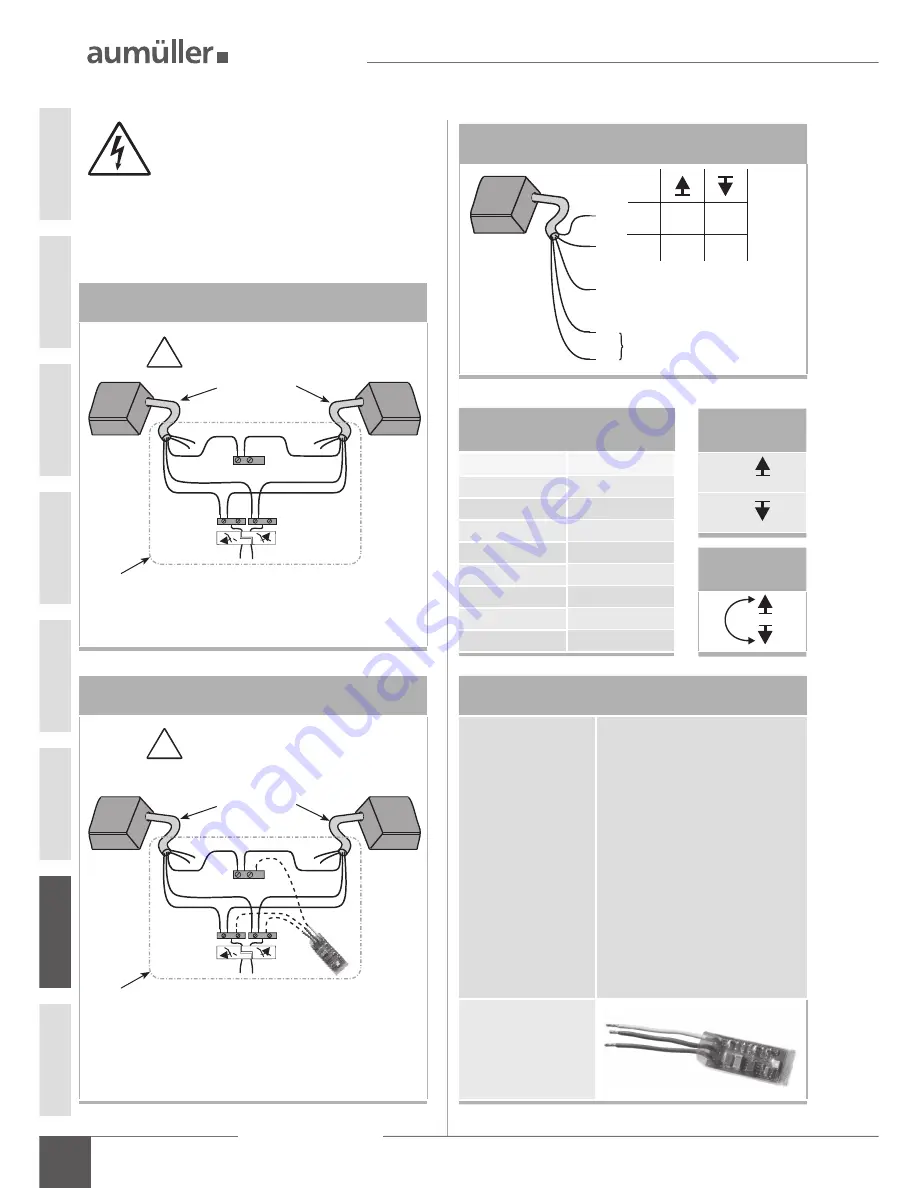
Multi-drive operation with master and slave
Multi-drive operation with M-COM
WH is used for communication,
with synchronized multi-drive operation.
WH is used for communication,
with synchronized multi-drive operation.
from control unit
from control unit
- +
+ -
- +
+ -
master
drive 1
slave
drive 2
BN
BN
BU
BU
24 V DC control
24 V DC control
WH
WH
connection
cable
connection
cable
junction box
site-supplied
junction box
site-supplied
Connection
Connection
drives do not work, if not connected
drives do not work, if not connected
!
!
Direction of
travel
OPEN
CLOSE
Polarity
reversal
+
+
-
-
Wire colour coding
Colour
DIN IEC 757
black
BK
white
WH
brown
BN
blue
BU
green / yellow
GN / YE
green
GN
violet
VT
grey
GY
Connection assignment
BN
+
-
BU
-
+
BN
VT
WH
GN
BU
WH is used for communication,
with synchronized multi-drive
operation
Version Z:
contact max. 24 V, 500 mA
(min. 10mA)
M-COM


