WASTEWATER TREATMENT
PLANT MODEL AT6 - AT50
5
6
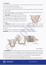
alignment), the inlet and outlet pipelines are connected (the pipes must be rigidly fixed and resting
on a solid foundation).
3.8. Built into the design position, the Unit is gradually filled with water, and the space between the
pit and the Unit is filled with sand layers (20-30 cm thick). Sand layers are carefully compacted (by
human body weight). Water is poured into the Unit to the level of the outlet pipe.
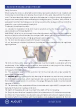
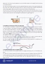
3.9. About 0.10 m from the top of the wastewater treatment plant is left uncovered with soil. The soil
surface around the Unit is formed with a slight slope away from the Unit, to prevent the accumulation
of storm water around the Unit, allowing its free flow (see Principal diagram 3).
4. Installation of the blower and the air supply pipe:
4.1. The location for the blower is selected in accordance with the technical requirements. The blow
-
er can be installed in a ventilated room (garage, storage, etc.) and outdoors (in the blower contain
-
er). The indoor-mounted blower must not come into contact with the wall or any other building
structure. If the blower is installed outdoors, it must be protected against moisture, rain and dust. A
blower container should not be installed in a place where water can run on it and accumulate. High
quality gaskets
MUST
be used in openings.
4.2. 220V-3X1.5 mm² electric cable is connected to the Unit.
4.3. The distance from the blower to the Unit must not exceed 5 m. In order to minimise pressure
losses, the turning points in the air supply line should be reduced to the minimum.
4.4. The air supply tube must be mounted in the protective shell and placed on a stable base, for
example, on undisturbed immobile soil.
5. Installation and connection of AUGUST BASIC:
5.1. The Unit controller can be installed indoors (in a garage, warehouse, etc.) or in the blower con
-
tainer.
5.2. Good air circulation should be ensured so that the maximum permitted temperature of the Unit
is not exceeded even during continuous operation at high ambient temperatures (max. 40 °C).
5.3. For indoor installation of the AUGUST BASIC Unit, two single-phase cables 3x1.5 mm MUST be
laid to the Unit.
Principal diagram 3
example
Содержание AT-10
Страница 20: ...WASTEWATER TREATMENT PLANT MODEL AT6 AT50 19 CERTIFICATE e x a m p l e ...
Страница 21: ...WASTEWATER TREATMENT PLANT MODEL AT6 AT50 20 e x a m p l e ...
Страница 22: ...WASTEWATER TREATMENT PLANT MODEL AT6 AT50 21 COMMENTS AND NOTES e x a m p l e ...
Страница 23: ...WASTEWATER TREATMENT PLANT MODEL AT6 AT50 22 COMMENTS AND NOTES e x a m p l e ...


