WASTEWATER TREATMENT
PLANT MODEL AT6 - AT50
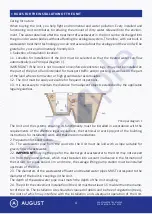
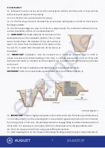
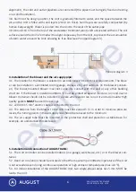
horizontal position. When turned down, the recirculating sludge will be pumped into the aeration
chamber, and when turned upwards, to the non- aerated chamber.
Valve partially open
– activated sludge must flow continuously; the flow should not be too weak or
too strong.
D-valve
Controls air volume to airlift 3. Flow from the non-aerated part of the reactor, chamber 1d to cham
-
ber 1a, must be visible.
The valve is partially opened.
Activated sludge must flow continuously, the
flow should not be too weak or too strong.
E-valve
Controls the amount of air into the diffuser (aeration) in the aerated part of the biological reactor.
Valve fully open (approx. 2.5 turns) – fine bubbling should appear on the surface of the aeration
chamber of the aerated activated sludge. Adjustment –
maximally open all the time.
Air supply F
Air supply from the blower.
The air distribution manifold has been factory-set during internal production control. If necessary,
you can set new settings, but first you have to close all the valves and then follow the instructions
above.
Flow controller
The flow controller ensures flow balancing under high instantaneous loads (bath, wash basin, etc.).
The discharge of water from the biological wastewater treatment plant through the calibrated hole
in the flow regulator is 3 l/min (180 l/h).
Blower
The blower is an electromagnetic diaphragm compressor, which is char
-
acterised by longevity, low maintenance timing and low maintenance
costs. The performance and power of the blower vary depending on the
model of the cleaning unit.
Diffuser
The number and length of aeration elements vary in wastewater treat
-
ment plants depending on the amount of oxygen needed to dissolve.
High quality aeration elements are made with a non-clogging mem
-
brane, polypropylene and stainless steel parts.
Airlifts
Mixing, circulation and activated sludge and wastewater recirculation in the system are ensured by
airlifts 1, 2 and 3.
Airlift 1 – mixing in the solids bag
Airlift 2 – sludge return from secondary settler
Airlift 3 – internal recirculation
10
9
example
Содержание AT-10
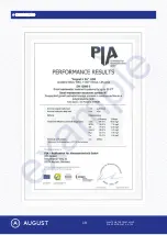
Страница 20: ...WASTEWATER TREATMENT PLANT MODEL AT6 AT50 19 CERTIFICATE e x a m p l e ...
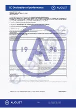
Страница 21: ...WASTEWATER TREATMENT PLANT MODEL AT6 AT50 20 e x a m p l e ...
Страница 22: ...WASTEWATER TREATMENT PLANT MODEL AT6 AT50 21 COMMENTS AND NOTES e x a m p l e ...
Страница 23: ...WASTEWATER TREATMENT PLANT MODEL AT6 AT50 22 COMMENTS AND NOTES e x a m p l e ...


