6
7
5.0 CONNECTING THE HARDWARE
• Turn off equipment that will be connected to the matrix. Mount the matrix in an
equipment rack if desired, using the included rack ears. Otherwise, place the
matrix on a flat surface with adequate ventilation and access to the front and
rear panels.
• Connect an HDMI approved cable from each HDMI source to an input of the
matrix. Cable lengths should be kept as short as possible.
• Since HDMI connectors can sometimes become loose, use locking HDMI
cables or mount the matrix to a flat surface and add strain relief tie-downs a
few inches away from every HDMI cable connector.
• If using locking cables, remove the Phillips screws above each HDMI port and
replace them with the hex-head jack screws provided. Plug in the HDMI cable
and insert the cable screws into the jack screw heads.
• Connect the outputs of the matrix to their destination devices.
• If you are using the infrared extension function, connect the extension IR
sensor cable and position the sensor.
• Connect the power adapter to the AC source and then to the matrix. Twist the
DC plug to 90 degrees in the matrix power port to lock.
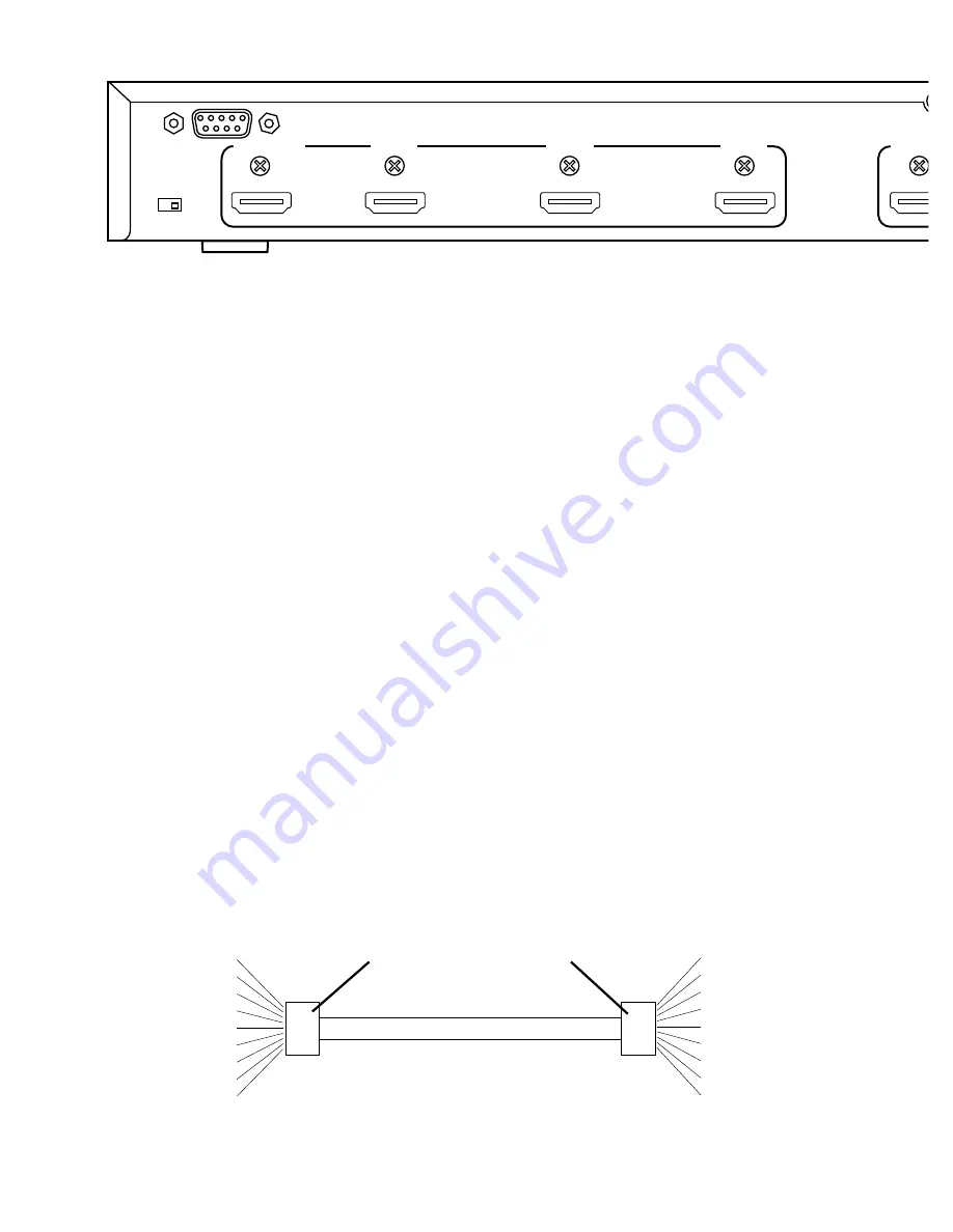
• If you are using the RS-232 control function, connect an RS-232 cable with
pinout as shown below.
Pin # Definition
Pin # Definition
NC
1
1
NC
Tx
2
2
Rx
Rx
3
3
Tx
NC
4
4
NC
GND
5
5
GND
NC
6
6
NC
NC
7
7
NC
NC
8
8
NC
NC
9
9
NC
SERIAL CONTROL CABLE
MATRIX
END
CONTROLLER
END
Model HMX-144 4x4 Video/Audio Matrix
Version 1.3
POWER
ZONE
1
SOURCE
1
2
3
4
HDCP
HDMI
DVI
ZONE
4
SOURCE
1
2
3
4
HDCP
HDMI
DVI
ZONE
3
SOURCE
1
2
3
4
HDCP
HDMI
DVI
ZONE
2
SOURCE
1
2
3
4
HDCP
HDMI
DVI
POWER
5V DC
IR
HDMI ZONE OUTPUTS
ZONE 1
SOURCE 3
SOURCE 2
HDMI SOURCE INPUTS
ZONE 4
ZONE 3
ZONE 2
SOURCE 4
SOURCE 1
INT / AUTO
EDID
RS-232


