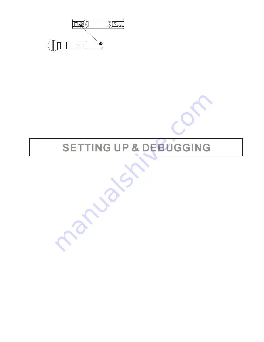
As shown in the above diagram, align the IR window of the AWX6952U to
the IR window of the AWR6952U with a distance of less than four inches
(10cm). The LCD screen will display “IR >>>”. When the frequency of the
AWX6952U is successfully set, the AWR6952U will return to the main
menu. Otherwise, the LCD screen will display “END”. When the “END” is
displayed, press any button to return to the main menu.
NOTE
: When “NO” is displayed, the AWR6952U will exit to the main menu
without any further action. Press the “POWER ON/OFF” button at any
time, the AWR6952U will exit to the main menu without saving any
setting.
1. After the AWM6952U system has been set up, keep both AWX6952U
transmitters powered off and turn both volume control knobs on the
AWR6952U receiver all the way to the minimum. Turn on the power of the
AWR6952U receiver. Both LCD screens will display the settings of the
previous set-up.
2. On the AWR6952U, tune both channels to have desired frequencies with
manual tuning or the auto scan (preferably auto scan). Adjust both
channels to have the SQ level of 5 dB and, then, return to the main menu.
At this stage, both transmitters are still off. If the radio frequency (RF)
signal level indicator shows an incoming RF signal received by the
AWR6952U receiver, there is an intermittent interference signal to the
receiver. Either adjust the SQ level higher (higher dB number) or change
the frequency with manual tuning or auto scan again. Repeat this
process until the RF signal is clear.
3. Turn on both transmitters. After the built-in CPU completes initialization,
check if the frequencies of both transmitters are the same as the
frequencies of both channels of the receiver. If any transmitter has
different frequency from that of the receiver, refer to the
SYNCHRONOUS FREQUENCY MATCHING section (on
) to
synchronize the transmitter frequency to the receiver frequency. Once
the frequencies for both transmitters are matched to the frequencies of
the receiver, adjust the volume control for each channel and the
AWM6952U is ready to be used.
page 16
-
17
-
SET
SET
SET
SET
SETTING UP & DEBUGGING


