


2 - 11
Installation Procedures
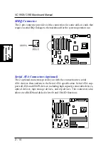
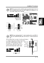
Wake-On-Ring Connector
The 2-pin connector allows you to link with your modem card which outputs
a WOR singal; the system can be turned on from the power-off status by a
remote phone call via the modem card.
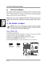
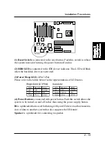
Power Connectors
The 20-pin male block connector is connected to the ATX power supply. The
4-pin male block connector is for the ATX_12V power use. All two connectors
are linked with your ATX power supply. The plug from the power supply will
only insert in one orientation because of the different hole sizes. Find the
proper orientation and push down firmly making sure that the pins are aligned.
Содержание VC19E
Страница 1: ...VC19G VC19E MAINBOARD MANUAL DOC No M02702 M02703 Rev A0 Date 9 2002 Part No 25 11657 00 ...
Страница 7: ...1 3 Overview The VC19G VC19E Mainboard ...
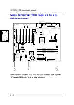
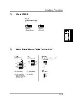
Страница 13: ...2 3 Installation Procedures 1 Clear CMOS 2 Front Panel Block Cable Connection ...
Страница 36: ...3 8 VC19G VC19E Mainboard Manual Advanced Chipset Features ...
Страница 52: ...3 24 VC19G VC19E Mainboard Manual This Page Left Blank for Note ...


