background image

CHAPTER 5: CHANNELS TAB

MDU Solutions

®

 – UCrypt

®

 IP to Analog 2

nd

 Generation – Installation & Operation Manual 

5-9

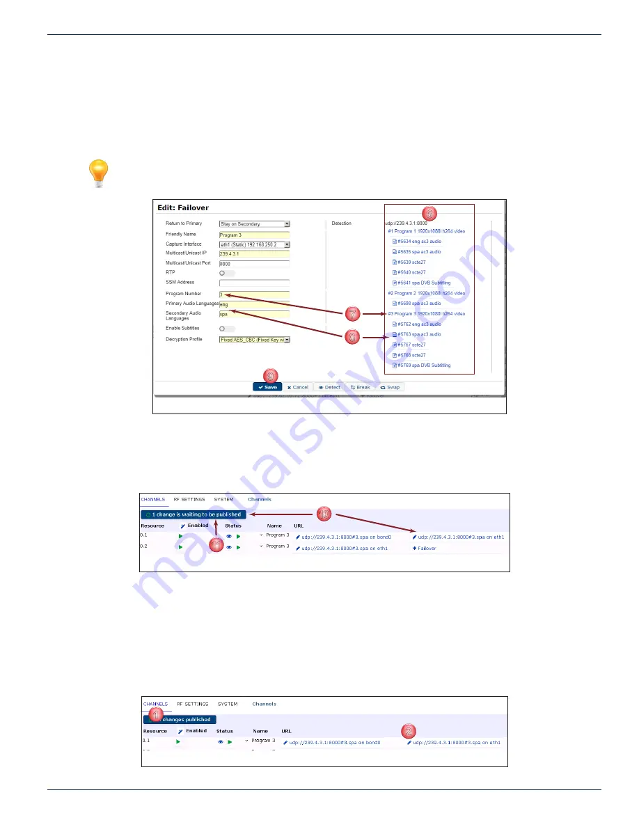
6.  The programs will be detected on the Multicast Group stream and displayed, Figure 5-18. Each program line listed is 

a link to add that program as the backup. An SPTS will only display one stream, and an MPTS will display all streams.  

7.  Click the desired program for backup. The selected program is added to the form.
8.  Click the desired language (if multiple languages are present, all are selected by default but you can manually select 

a single language). The selected languages are added to the form.

9.  Click 

Save

 when finished.

NOTE:  Mousing over the configuration fields shows tool tips for help in configuration.

10.  The backup stream is added to the resource line, but is not yet active as the publish button announces 

‘1 Change is 

waiting to be published’

Figure 5-19.  

11.  Click the 

Publish

 button.

The stream is now ready to perform as backup to the primary stream.

5.9  Manually Activate the Backup Stream

The primary and secondary streams may be swapped manually.

Procedure

This procedure explains how to manually activate the backup feed.

1.  Select the 

Channels

 tab if it isn’t already selected, Figure 5-20.

2.  Click the resource’s backup feed 

URL

.

6

7

8

9

Figure 5-18: Save Failover Form

10

11

Figure 5-19: Backup Channel Added But Not Published

1

2

Figure 5-20: Select Backup URL

Содержание IP2Agen2

Страница 1: ...Patent Pending UCrypt IP2Agen2 Installation Operation Manual UCrypt IP to Analog 2nd Generation ...

Страница 2: ...ervice outage NOTE This symbol indicates that there is helpful related information available in this note or elsewhere in the guide Although every effort has been taken to ensure the accuracy of this document it may be necessary without notice to make amendments or correct omissions Specifications subject to change without notice Any use of the UCrypt product directly or indirectly for the decrypt...

Страница 3: ...RU Device 3 4 3 9 Install the 2RU Device 3 8 3 10 Equipment Safety Grounding 3 9 3 11 AC Power Supplies 3 10 3 12 DC Power Supplies 3 11 3 13 Power Supply Redundancy 3 11 4 STARTUP 4 1 4 1 Chapter Contents 4 1 4 2 Configure Your Computer 4 1 4 3 Device Connections 4 1 4 4 Use a Browser to Login 4 2 4 5 Principle UI Features 4 3 4 6 Configure Network Settings 4 4 4 7 Select Analog Channel Plan 4 4 ...

Страница 4: ...4 User Configuration 6 14 6 5 Location 6 15 6 6 Current Date 6 16 6 7 Power 6 17 6 8 Firmware 6 17 6 9 Monitoring Alerts 6 18 6 10 EAS 6 18 6 11 Configuration Backup 6 19 6 12 Diagnostics 6 21 6 13 Debugging 6 21 7 RF SETTINGS 7 1 7 1 Chapter Contents 7 1 7 2 About RF Settings Page 7 1 7 3 Select Active Channel Plan 7 2 7 4 Download a Channel Plan 7 3 7 5 Upload a Custom Channel Plan 7 4 7 6 Set C...

Страница 5: ...operation use the power cord supplied for operation from a 115 VAC source b For 230 VAC operation use the power cord supplied for operation from a 230 VAC source GROUNDING OR POLARIZATION Electrical grounding and polarization means must not be defeated POWER CORD PROTECTION Care must be taken during installation to route or arrange the power supply cord to prevent and avoid the possibility of dama...

Страница 6: ...CHAPTER 1 SAFETY 1 2 MDU Solutions UCrypt IP to Analog 2nd Generation Installation Operation Manual This page intentionally left blank ...

Страница 7: ...r in the next section 2 4 Controls Indicators The products are designed to be plug and play and will be in a powered on state when the power cord is plugged in There may be instances where it is desired to reboot or power down the devices manually and recessed switches to enable that are located on the front panel a detailed view of which is shown in Figure 2 3 1RU and Figure 2 4 2RU Indicator lig...

Страница 8: ...ive activity when flashing PWR Indicator LED Green Indicates power is being supplied to the system s power supply units This LED should be illuminated when the system is operating RST Recessed Button Reset Switch Used to warm reboot the Device Functionally equal to a reset button on a computer PWR Recessed Button Power Switch This is the main soft power switch and is used to apply or remove power ...

Страница 9: ...itch used between IP2A Devices and the Management Computer will require the following ports to be opened both Inbound and Outbound NOTE Failure to open these ports may result in communications problems between the management computer and IP2A Devices Table 2 6a Ports to Open on Switch Port Number Transport Protocol 80 TCP HTTP 443 TCP HTTPS ...

Страница 10: ...CHAPTER 2 OVERVIEW 2 4 MDU Solutions UCrypt IP to Analog V2 Installation Operation Manual This page intentionally left blank ...

Страница 11: ... securely before operation is initiated 3 3 Precautions 3 3 1 Electrical Precautions Basic electrical safety precautions should be followed to protect yourself from harm and the Device chassis from damage Be aware of the locations of the power on off switch on the chassis as well as the room s emergency power off switch disconnection switch or electrical outlet If an electrical accident occurs you...

Страница 12: ... in the rack before you install the rails Install the heaviest components on the bottom of the rack first and then work up Use a regulating uninterruptible power supply UPS to protect the Device from power surges voltage spikes and to keep your system operating in case of a power failure Allow any power supply modules to cool before touching them 3 3 4 Rack Precautions Ensure that the leveling jac...

Страница 13: ...compromised The equipment is designed to operate to specification in an ambient temperature of 0 C to 40 C 35 F to 104 F however normal room temperature is recommended to ensure long term operation of the equipment If equipment is installed in a closed or multi unit rack assembly the operating ambient temperature of the rack environment may be greater than room ambient Therefore consideration shou...

Страница 14: ...l the Device chassis to the bottom of the rack first to avoid the rack becoming top heavy 3 8 1 Identifying the Rack Rail Sections The 1RU Device chassis includes two rail assemblies in the rack mounting kit Each assembly consists of two sections An inner chassis rail secured to the chassis front part is factory installed extension is field installed an outer rail that secures to the rack and an o...

Страница 15: ...ver rack Attach the inner rail extension to help support the rear of the chassis within the rack 1 Place the inner rail extensions on the side of the chassis aligning the hooks of the chassis with the inner rail extension holes Figure 3 2 Make sure the inner rail extension faces outward just like the pre attached inner rail 2 Slide the extension toward the front of the chassis latching it onto the...

Страница 16: ...in order to be secured to the rack 2 Adjust both sections of the outer rail to the proper length so that the rail fits snugly within the rack Figure 3 4 3 Secure the longer section of the outer rail to the of the front rack rails with two 10 32 rack screws 4 Secure the shorter section to the rear rack rails with two 10 32 rack screws 5 Repeat steps 1 4 for the remaining outer rail Secure to rack f...

Страница 17: ...e chassis rails with the front of the outer rack rails then slide the chassis rails into the rack rails keeping the pressure even on both sides you may have to depress the locking tabs when inserting When the Device has been pushed completely into the rack you should hear the locking tabs click into the locked position 4 Insert and tighten the screws that hold the front of the Device to the rack i...

Страница 18: ...ctions to suit the rack unit you are using NOTE The illustrations in Figure 3 6 and Figure 3 7 are for general guidance purposes only Always install the Device chassis to the bottom of the rack first to avoid the rack becoming top heavy 3 9 1 Mount the Chassis 1 Confirm that you have the four mounting screws required to mount the chassis into a rack 2 Align the thru holes of the chassis with the t...

Страница 19: ...dent means even when the power supply cord or wires may be disconnected temporarily A ground connection screw terminal is provided on the rear panel to conveniently effect such a connection 3 10 1 Ground Connection The supplementary equipment grounding conductor is to be installed between the rear panel ground screw and earth that is in addition to the equipment ground conductor in the power suppl...

Страница 20: ...building structure 3 11 3 Provision of Electrical AC Power Outlet An AC electrical power outlet of appropriate type and rating shall be provided near the location where the unit is installed and easily accessible such that the provided power supply cords may be routed in an appropriate manner without the use of extension cords between the receptacle and the chassis Alternately the chassis shall be...

Страница 21: ...ced The disconnect must be turned off for BOTH power modules before removing supply wires from the module terminal blocks when replacing a power supply module or otherwise servicing the unit 3 13 Power Supply Redundancy For the redundant power supplies either power module on its own can provide the required power safely if one fails To retain the redundancy feature replace a failed power module as...

Страница 22: ...it Power module failure will be indicated by the alarm being sounded and the green status light on the module will no longer be lit This power module may be replaced by first disconnecting the DC power at the external disconnect device for BOTH power modules then use a 2 Phillips screw driver to remove the DC wires from the failed module terminals Release the module by pressing to the right on the...

Страница 23: ...ically with the standard ATX Networks default IP address of 192 168 0 23 assigned to port eth0 Before connecting each Device to the management switch or network the IP addresses must be re configured for your network See Figure 4 1 and Figure 4 2 for the location of the ports 1 Connect the Management Computer to eth0 The UCrypt Devices have eth0 network ports factory assigned IP address 192 168 0 ...

Страница 24: ...ypt_guest_password No configuration Just monitoring PASSWORD WARNING ATX Networks strongly recommends that the factory default passwords be changed immediately upon Device initialization The ability to dismiss or disable password warnings in the GUI are intended only for lab test environments with no internet connectivity to the Device eth0 192 168 0 23 Management Management Computer 192 168 0 50 ...

Страница 25: ... changed Simply click the URL and edit as required 5 The Publish Button is used to apply all changes made on the Channels and RF Settings tabs The System tab and Network configuration pages have their own buttons to apply changes 6 A control to bulk enable a selected group of resources Figure 4 7 7 A group of controls to bulk configure a selected group of resources 8 Click the Eye icon to enable a...

Страница 26: ...on page 6 2 for configuration information 4 7 Select Analog Channel Plan Refer to 7 3 Select Active Channel Plan on page 7 2 for configuration information 4 8 Setup Analog Channels Refer to 5 10 Setup the Output Analog Channels on page 5 10 for configuration information 4 9 Add an Input Stream Refer to 5 7 Add an Input Stream on page 5 4 for configuration information ...

Страница 27: ...before they take effect The number of changes to be published are noted inside the Publish Button just below the header Figure 5 1 just click the button to apply the changes Changes to all channels or groups of channels such as starting stopping enabling and disabling may be made simultaneously with the Mass Configuration Button see Figure 5 1 5 3 Status Icons Explained There are several types of ...

Страница 28: ... be enabled before use Enabling turns on the RF output for each resource and may be done individually by clicking the small grey square icon for each resource which then changes into a small green triangle icon see Figure 5 4 To enable a group of channels at once click the Wand icon nearest the Enabled header and refer to 5 6 Mass Configuration on page 5 3 To reveal expanded information about the ...

Страница 29: ...g of streaming of multiple resources Used for enabling or disabling multiple resources 5 6 2 Aspect Ratio Tool Used for changing Aspect Ratio of multiple resources 5 6 3 Audio Mode Tool The Audio Mode tool is at the bottom of the page below the Audio Gain column Used for changing audio mode between Stereo Mono of multiple resources 5 6 4 Audio Gain Tool Used for adjusting audio gain of multiple re...

Страница 30: ...is shown beside the 6 Click Save You are returned to the Channels tab where the publish button announces that x Changes are waiting to be published Click the Publish button 5 7 Add an Input Stream The Channels tab presents the input streams streaming status of each resource and provides access to configuration pages If any channels are to be decrypted that will be specified as the channel is added...

Страница 31: ...tem Primary Audio Language String string If specified the comma separated set of languages to match select when choosing PIDs If not specified the first audio PID will be used If multiple the Device will try each one in order of listing until it can sync to one language and will then use that one language If none are listed it will default to the first Audio PID found regardless of the language No...

Страница 32: ...dded Alternately click only the language you want 10 The selected program and language are added to the form 11 Click Save 12 The Resource needs enabling click the Enable Button icon to turn it to a green triangle see Figure 5 12 13 The new stream URL values added to the resource are not yet live Figure 5 13 and the publish button announces that 3 Changes are waiting to be published The new stream...

Страница 33: ...ined Failover to the backup will automatically occur when the primary feed is unavailable The return to primary can be defined as automatic return to primary or stay on secondary Feeds may also be manually swapped If any channels are to be decrypted on the output that will be specified as the channel is added or edited so the Decryption Profile must be defined beforehand see Decryption Profiles on...

Страница 34: ...ger The backup stream IP Port from which to pull the stream RTP Tick box Switch Tick select if the source uses RTP leave unticked unselected for regular UDP SSM IP Address Source Specific Multicast IP When specified only content sent by this IP is processed Program Number Integer Program of backup stream Primary Audio Language String string If specified the comma separated set of languages to matc...

Страница 35: ...dded to the form 9 Click Save when finished NOTE Mousing over the configuration fields shows tool tips for help in configuration 10 The backup stream is added to the resource line but is not yet active as the publish button announces 1 Change is waiting to be published Figure 5 19 11 Click the Publish button The stream is now ready to perform as backup to the primary stream 5 9 Manually Activate t...

Страница 36: ...desired 5 10 Setup the Output Analog Channels The UCrypt Device comes pre configured with all channels defined but any channel may be re assigned easily by typing in the new channel number Duplicates are not allowed so first delete any channels to be moved to avoid duplication 1 Click the Channels tab if it is not already selected Figure 5 23 2 The channel assignments within the chosen plan are pr...

Страница 37: ...ofiles may be setup and saved for simple activation Decryption Profiles may be applied on any or all of the resources on a channel by channel basis The types of decryption include ECB Electronic Codebook and CBC Cypher Block Chaining whereas the decryption profiles describe the parameters to be used for decryption Decryption Profiles are created or accessed from the bottom of the Channels page see...

Страница 38: ...already selected Figure 5 28 2 At the page bottom click Scrambling Profiles 3 Click Fixed Key Figure 5 29 to create a new Fixed Key Decryption Profile 4 Enter a name for the new profile This will be used to identify it within the GUI 5 Select Decryption type from the drop down menu Fixed Key with AES CBC or Fixed Key with AES ECB In the following example we show creation of the CBC key but ECB key...

Страница 39: ... the changes made on this form Cancel Button Cancels changes made and returns to the previous window 9 If the decryption is to start at a future time click the Start Timestamp dialog see Figure 5 31 which opens a clickable Time Date configuration window Figure 5 32 10 In the Time Date dialog configure the start date by clicking the day of the week and use the forward and backward arrows to choose ...

Страница 40: ... click the Download link Figure 5 35 The profile is downloaded to your usual browser downloads folder 5 To import or upload an existing Decryption Profiles file in either format to the Device click the Choose File button to browse to the file using the file explorer window that opens 6 For CSV files only click the Ignore Unknown switch to instruct the Device to ignore any unknown values within the...

Страница 41: ...form Global settings and includes the categories of Network Configuration User Configuration Firmware Upgrades System Time SNMP and more 6 1 Chapter Contents Network Configuration Ethernet Interface Bonding User Configuration Location Current Date Power Firmware Monitoring Alerts EAS Configuration Backup Diagnostics Debugging Figure 6 1 System Tab Part 1 ...

Страница 42: ...ion Operation Manual 6 2 Network Configuration From this page Figure 6 3 you may edit the physical Ethernet port IP addresses and create VLANs NOTE Mousing over the page fields shows tool tips for help in configuration Figure 6 2 System Tab Part 2 Figure 6 3 Network Configuration Page ...

Страница 43: ... In The interface which will be used for IP input if a specific interface is not set when defining the source This role is only useful for Device models which accept IP input An interface defined as External IP In may have the Management GUI SNMP Access Support Access ports enabled if desired via the respective toggle switches 6 2 2 Edit a Network Interface Your application of the Server will like...

Страница 44: ... DHCP requests IP Address IP Address IP Address v4 or v6 Network Mask IP Subnet Mask Network Mask ffff ffff ffff or 255 255 255 0 format Default Gateway IP Address Routing Gateway for the Interface DNS Server IP Address DNS Server only used if specified here DNS Search Domain URL As required by your network NTP Server IP Address URL Network Time Protocol server to which to synchronize this Device ...

Страница 45: ...terface occurring over a period of time Procedure This procedure describes monitoring of the network performance histogram 1 Click the System tab if it isn t already selected Figure 6 9 2 Click Configure Network under Network Configuration section 3 A Histogram of network data sent and received over each individual interface is updated every 10 seconds and shows continuous history for as long as t...

Страница 46: ...Configuration section 3 Click the Ping button on any Ethernet port to initiate the Ping function on that interface Figure 6 12 4 Enter the Target IP address of the device to be pinged Figure 6 13 5 Click the Ping button 6 The ping results are shown Figure 6 14 To continue with another ping to this address click Ping again 7 Alternately try another target by entering its IP address then click Ping ...

Страница 47: ...ted Figure 6 15 2 Click Configure Network under Network Configuration section 3 Click the Edit Address Filters button Figure 6 16 4 In the window that opens enter the IPv4 addresses or networks in CIDR notation that will be allowed or denied access to this machine GUI in the corresponding dialog box Figure 6 17 CIDR Notation examples CIDR 192 168 100 0 32 is the same as 192 168 100 1 255 255 255 2...

Страница 48: ...but it will be necessary to have a registered domain name for the Device Detailed information about obtaining a certificate is available at https letsencrypt org Procedure This procedure explains how to add an Acme SSL Certificate to the Device 1 Click the System Tab if it isn t already selected Figure 6 19 2 Click Configure Network under Network Configuration section 3 Click the ACME SSL Certific...

Страница 49: ... own self signed SSL certificates This is useful if you already have an internally trusted self signing authority Procedure This procedure explains how to install an SSL Certificate to this device 1 Click the System Tab if it isn t already selected Figure 6 22 2 Click Configure Network under Network Configuration section 3 Click the SSL Certificate button Figure 6 23 4 To upload an SSL Private Key...

Страница 50: ...p a VLAN system on your equipment 1 Click the System tab if it isn t already selected Figure 6 25 2 Click Configure Network under Network Configuration section 3 Click VLAN on the eth1 or other interface to add a VLAN for remote Device management over the network interface 4 Edit or fill in the VLAN settings form Figure 6 27 according to Table 6 2a and your system requirements 5 Click Save when fi...

Страница 51: ...ongly encouraged to leave this enabled on at least one interface 6 VLAN is added to Interfaces but is not yet activated Figure 6 28 7 Click Apply Configuration to activate changes 8 If it is required to edit an existing interface click the Pencil icon for each interface to be edited Always click the Apply Configuration button after all changes have been made 6 3 Ethernet Interface Bonding A featur...

Страница 52: ...the System tab if it is not already selected Figure 6 29 2 Click Configure Network under Network Configuration section 3 Click the Edit Bond icon on the eth1 interface to add a Bond for this NIC Figure 6 30 4 Select Active Backup as the Bonding Method and the Secondary NIC to bond with from the choices available in the drop down menus Figure 6 31 See Table 6 3a Bonding Modes Description on page 6 ...

Страница 53: ... Secondary interface for the bond in Active Backup mode member in other modes Bonding Mode Dropdown Menu Bonding mode used to aggregate the interfaces See Table 6 3a Bonding Modes Description on page 6 11 Use DHCP Client Tick Box Switch Un Ticked Grayed out for static IP address tick checked for DHCP IP Address IP Address IP Address IPv6 or IPv6 Network Mask Integer Network Mask ffff ffff ffff or ...

Страница 54: ...guration button 6 4 User Configuration Here you may manage users adding new deleting setting permissions PASSWORD WARNING ATX Networks strongly recommends that the factory default passwords be changed immediately upon Device initialization The ability to dismiss or disable password warnings in the GUI are intended only for lab test environments with no internet connectivity to the Device Procedure...

Страница 55: ...nfigurable Value First Name String The first name of the user This is mandatory Last Name String The last name of the user This is mandatory Email Address String The email address of the user This is mandatory Active Tick Box Switch A switch to deactivate the user while retaining the user in the database for later reactivation Groups Selection dialog The user may be assigned permissions as a Monit...

Страница 56: ...header when logged in 1 Click the System tab if it isn t already selected Figure 6 40 2 Under the Location section enter a Name for the Physical Location to identify the unit to the user when logged in There is no limit to the number of characters as the line extends across the header to accommodate the text string 3 Click Set Location 4 The name will be displayed in the header when logged into th...

Страница 57: ...edule a shutdown to occur in 1 minute Power off the system until it is manually power cycled This takes a unit out of service until field personnel arrive for a power recycle May be used if an errant system configuration is causing unintended channel outages and must be removed from service Cancel Shutdown Button Cancel pending shutdown or reboot if a shutdown was scheduled and it is decided to no...

Страница 58: ...mpile into the remote manager system click UCrypt IP2A MIB link 2 Enter the SNMP parameters in the form 3 Click the Set SNMP button 4 To test that the settings are correct send a test message to the remote manager click Test SNMP Traps 6 10 EAS The EAS section Figure 6 46 allows EAS Emergency Alert System configuration for messaging and program substitution but there needs to be a Details Channel ...

Страница 59: ...nt sent by this IP is processed Details Program Integer Program number to use for the Details Channel stream during force tune Location Filter Integer Integer etc Use the location filter to ensure the alert is activated only when appropriate for your county or state FIPS codes for location are in numeric format SSCCC or XSSCCC where SS is the FIPS state ID integer CCC is the FIPS county ID integer...

Страница 60: ...Click OK to proceed to save the date stamped file in the folder usually used by your browser downloaded files Your browser may present this in a slightly different way 6 11 2 Upload or Restore a Backup Procedure This procedure explains how to restore a previously saved backup file to the Device 1 Click the System tab if it isn t already selected Figure 6 51 2 In the Configuration section click the...

Страница 61: ... Device but not yet applied 6 Click the Channels tab Figure 6 54 7 The Publish button announces 1 change is waiting to be published Click the Publish button The uploaded configuration is taken live 6 12 Diagnostics The Device can download a diagnostics file for troubleshooting purposes Figure 6 55 This is not a human readable file Use this feature only under the guidance of ATX Networks Technical ...

Страница 62: ...the System page click System Log under the Debugging section Figure 6 56 The log is displayed in the browser and may be copied by dragging across the text and copying to a text editor 6 13 2 EAS Log The Device produces an EAS log of the internal functions Figure 6 58 It can be long but may also help to understand issues that can arise with EAS It is on by default showing the switch turned on blue ...

Страница 63: ...levance 4 The plan Friendly Name identifies the plan in this UI 5 The green Dot indicator identifies the active plan 6 The Channel Plan and Video Standard is changed with a menu Select from available plans and standards 7 The Channel Count for information only is the number of channels available for each plan 8 You can Delete a Channel Plan by clicking the x adjacent the relevant plan 9 The Analog...

Страница 64: ...l Interval Test Signals inserted on these analog channels 5 Click Save 6 The active plan is indicated by a green indicator adjacent the plan 7 It is necessary to Publish changes made to the Plan on the Channels page Click the Channels tab Figure 7 3 8 The Publish button shows 1 change is waiting to be published Click the Publish Button This applies the change to the Device 9 After publishing a reb...

Страница 65: ...cedure explains how to download a channel plan in a comma delimited spreadsheet format to your PC 1 Click the RF Settings Tab if it isn t already selected Figure 7 5 2 Click the name of the existing plan to be downloaded from the choices presented 3 A summary of channels included in this plan are listed Figure 7 6 4 Click the Download button 5 Select Save File Figure 7 7 to download the file via y...

Страница 66: ...dified channel plan from your PC 1 Click the RF Settings Tab if it isn t already selected Figure 7 8 2 Click New 3 Enter the Plan Name for the new plan Figure 7 9 This name identifies the plan in the UI only 4 Click Browse 5 Browse to your custom Channel Plan file with the file manager window that opens Figure 7 10 the appearance of which depends upon the browser you are using 6 Click Open this ma...

Страница 67: ...ls can be set to CW for test purposes They are controlled in groups of 20 channels so if there are 60 channels in your device this must be done to all 3 cards to get all channels set to CW Procedure This procedure outline how to set the RF output carriers to CW mode 1 Click the RF Settings Tab if it isn t already selected Figure 7 14 2 At the page bottom for the RF Output card There may be up to 3...

Страница 68: ...ave If more RF Output cards need to be set to CW Mode return to step 2 and repeat for all cards 5 The changes need to be published Click the Channels tab Figure 7 16 6 The Publish button announces X change is waiting to be published Click the Publish button to make this plan live 5 6 Figure 7 16 Publish the Mode Change ...

Страница 69: ...factory Digital Video Products DVIS DigiVu UCrypt VersAtivePro TECHNICAL SUPPORT Tel 905 428 6068 press 3 then press 1 Toll Free 800 565 7488 press 3 then press 1 USA Canada only Email digitalvideosupport atxnetworks com CUSTOMER SERVICE ATX Networks 1 501 Clements Road West Ajax ON L1S 7H4 Canada Tel 905 428 6068 Toll Free 800 565 7488 USA Canada only Press 1 for Customer Service Fax 905 427 1964...

Страница 70: ...n Canada Rev 09 17 ANW1154 1 501 Clements Road West Ajax ON L1S 7H4 Canada Tel 1 905 428 6068 Toll Free 1 800 565 7488 Fax 1 905 427 1964 Toll Free Fax 1 866 427 1964 www atxnetworks com support atxnetworks com ...

Отзывы: