


11/10/
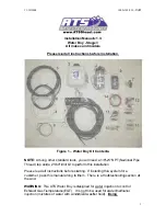
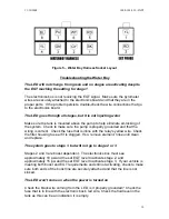
Figu
1
2
2
2
2
2
N
n
3
2
2
/2008
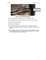
ure 2 - Tank
mou
9. Attach th
0. Extendin
RED 12V
on the pu
1. Mount th
manifold
2. Connect
to the po
the supp
and a
15
3. Connect
to the po
the supp
and the
3
4. Connect
ring term
Note:
If you
ozzles and
0 regarding
5. Remove
intercool
intake sy
engine.
6. Drill three
spaced.
from the
"mock-u
k mounted
nted below
he
Black
wi
ng from the
V
” extends
ump.
he solenoid
using supp
the
Yellow
ositive termi
plied fuse ho
5A
fuse.
the
Yellow
ositive termi
plied fuse ho
30A
fuse.
the group o
minal.
u have a Do
boost line
g the boost
the Intake
er pipe and
ystem is apa
e (3) 21/64
Keep in m
manifold a
up" the noz
in front-pa
w on a sup
ire from the
Water Boy
from
Relay
and relay a
plied hardw
w
wire from
inal on the
older in a co
w
wire from
inal on the
older in a co
of
Black
w
odge with a
fitting. Ski
line.
manifold fr
d engine to
art. Debris,
" holes in th
ind that the
good dista
zzles. Make
assenger s
pport (Dura
e pump to a
y harness, a
y 1
. Conne
assembly a
ware.
Relay 2
la
battery. Cu
onvenient l
Relay 1
la
battery. Cu
onvenient l
ires to a go
an ATS Arc-
p steps 25,
rom the veh
prevent de
small or la
he manifold
e nozzles an
ance.
Place
e sure you
side corne
amax)
a chassis gr
a red wire la
ct this
Red
as near as p
beled “
TO
ut the
Yello
ocation. U
beled “
TO 3
ut the
Yello
ocation. U
ood ground
-Flow, it is p
26, 27 but
hicle. Make
ebris from e
arge, can se
d in position
nd the supp
e the mani
u have clea
1000-
er of bed an
round
abeled, “
TO
wire to the
practical to
15A FUSE
ow
wire and
se the hold
30A FUSE
ow
wire and
se the hold
using the a
pre-tapped
t you must f
sure to blo
entering whi
everely dam
ns that are
ply lines wil
fold on the
arance befo
-102-930 - INS
nd pump
O PUMP-
e
Red
wire
the intake
BATTERY
d splice in
der provided
BATTERY
d splice in
der provided
attached
for the
follow step
ock or cover
ile the
mage the
properly
ll extend ou
e engine to
ore drilling
ST
5
Y
”
d
Y
”
d
r
ut
o
g.
Содержание Water boy
Страница 9: ...11 10 2008 1000 102 930 INST 9...