ATS Water boy Скачать руководство пользователя страница 4

11/10/2008  

1000-102-930 

INST 


4

9.  Find a suitable/visible location to mount the L.E.D. such as the dash or a 

gauge pillar. 

10. Drill a hole just large enough to fit the plastic sleeve through and push the 

LED through to secure it. A 1/4" drill bit will work best. 

11. Find a suitable location for the supplied power switch and install it. The 

switch requires a 13/16” hole to mount properly. 

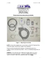
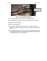
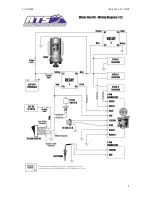
12. Feed the four-wire group (

Red, Black, Yellow, Blue

) extending from the 

Water Boy harness through a rubber grommet in the firewall into the cab. 

13. Connect  the 

Red

 wire of the four-wire group to the center terminal of the 

switch with a spade connector. The wire should be labeled; “To Middle 
Terminal Switch”. 

14. Connect the remaining three wires of the four-wire group to the L.E.D. 

color for color.  

15. Connect the supplied 

Black 

wire to the brass-colored terminal of the 

switch with the spade connector.  Connect the other end of the black wire 
to a good ground under the dash.  

16. Connect the supplied 

Pink

 wire to the remaining switch terminal and 

attach it to a 12V source under the dash that is only energized when the 
key is turned on.  Use a voltmeter to find a suitable wire.   

17. At a convenient location under the dash, cut the 

Pink

 wire connected to 

the switch and splice in the supplied in-line fuse holder.  Use the supplied 
15A fuse.   

18. Find suitable locations for both the pump and tank.  Depending on the size 

of the tank and the vehicle make, a spot under the hood might be hard to 
find. If the tank cannot be mounted in the engine compartment, mount the 
tank in the bed and the pump on the frame rail.  Mount the tank above the 
pump so that gravity will feed the pump (this will help eliminate "air-
locking" of the pump).  If the tank will be mounted in the bed, mount it on 
the same side as the intake manifold (Cummins- Driver’s side, Duramax-
Passenger’s side).  This will make it easier to route the 3/8” plastic line. 

Содержание Water boy

Страница 1: ...drill bit to pe s before sta al along to t ter Boy is d e EGT It r with winds on Manual Boy Stag es and mo ructions be ater Boy Ki you will ne erform this arting If in them The designed fo is not to...

Страница 2: ...active The third stage will activate when the EGT probe senses a temperature above the box setting AND the boost sensor measures approximately 15 psi or 30 see Boost Level Setting section of boost or...

Страница 3: ...k that no other vehicle systems are damaged during installation Installation 1 Please make sure no parts are missing from ATS Stage 3 WaterBoy Kit A complete corresponding list of parts can be found o...

Страница 4: ...the switch with the spade connector Connect the other end of the black wire to a good ground under the dash 16 Connect the supplied Pink wire to the remaining switch terminal and attach it to a 12V s...

Страница 5: ...ebris holes in th ind that the good dista zzles Make assenger s pport Dura e pump to a y harness a y 1 Conne assembly a ware Relay 2 la battery Cu onvenient l Relay 1 la battery Cu onvenient l ires to...

Страница 6: ...onnecto m the T to ot have a s the 21 64 d ting before ctronics boa st line fitting 31 d intake ma Ford 6 0L m T tings on the lent size and po ds quire a boos oft 1 8 line ors then sp the boost p soft...

Страница 7: ...area so it is easy to check and clean in the future 35 Run 3 8 line from the filter to the tank 36 With the tank in place and 3 8 lines installed route the Red harness wires labeled To Tank along the...

Страница 8: ...nk check for leaks 40 Reconnect the battery s 41 Test drive the vehicle with the system armed The LED will be green when armed yellow during stage 1 orange during stage 2 and red during stage 3 42 In...

Страница 9: ...11 10 2008 1000 102 930 INST 9...

Страница 10: ...hat the wiring is correct Check the fuse that is inline with the relay s yellow wire Check the filter housing to see if it is clogged If so remove element rinse until clean and replace The system goes...

Страница 11: ...Body and ATS High Performance Transmission along with our full line of power enhancers Please call or e mail our Technical Service Department 8 00am to 5 30pm Mountain Standard Time Monday through Fri...

Страница 12: ...NPT Fitting A6MC6 MG 4 Self Tap Screw 85241D 1 Self Tap Screw 84930D 1 16 14 Ring Connector 35776 3 Reservoir Tank Assembly 1 Tank Cap 070316AE 1 3 8 Push In to 3 8 NPT Fitting A6MC6 MG 6 Washer 88445...

Страница 13: ...ng HSR316 1 ATM Fuse Holder ATMFH12 1 15A ATM Fuse ATM15 1 Switch 3 Female Blade Connectors 86061 4 18 AWG Wire Black GPT 18 00 4 18 AWG Wire Pink GPT 18 11 1 16 14 Ring Terminal 25262 13 Nozzle Bundl...

Отзывы: