background image

Step 1:

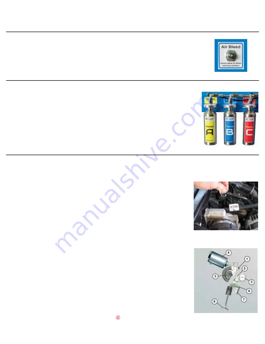
 Push the air bleed valve on the back of the 3C. This will allow the air 


pressure to vent to the atmosphere before removing the chemical reservoirs.

Step 2:

 To remove and fill the 3 reservoirs on the back of the machine unscrew 


the reservoirs counter clockwise. Look into the reservoirs and make sure 


the chemical has all been delivered to the engine. Make sure 3C Chemical 


A, B and C are put in the specific reservoir for Chemical A, B and C. Hand 


tighten the reservoirs so the labels are facing you. NOTE: Do not cross 


contaminate the chemicals. 

WARNING: Do not use any other chemicals in 


the 3C; immediate damage to the 3C will result.

Connecting your 3C to a vehicle

Step 3:

 Find a common vacuum or induction port on the engine that is behind 


the throttle valve. This should be the 

Purge Control port


or PCV port. If 


the engine is not equipped with a common port 

DO NOT CLEAN 

 ENGINE.


This can, or will, result in engine damage. 

The engine port 


must allow equal chemical delivery to all the cylinders in the engine as 


the chemical is being applied to the engine. On some engines there is a 


sensor located in the center of the intake manifold, that will allow for 


equal distribution, that can be used. If this sensor is a Manifold Absolute 


Pressure (MAP) sensor and there is no Mass Air Flow (MAF) sensor on 


the vehicle, then removing this sensor will not allow the ECM the data 


needed to calculate the air weight. 

IN THIS CASE DO NOT USE THIS 


SENSOR PORT.


NOTE: THE VACUUM PORT MUST BE LOCATED 


BEHIND THE THROTTLE PLATE. 

Take the time to find a centrally 


located induction port. 

Something close to the throttle body, 


preferably the purge port.


NOTE: Make sure the port you use opens 


into the intake manifold and preferably straight through into the intake. 


For example, new GM vehicles have the purge valve mounted directly 


on the intake manifold. There is a 90 degree bend directly under the 


purge valve. This is not an optimal location so you will need to find a 


different port, such as the PCV port. 

NOTE: never use a port that is


located on one side or on the end of the manifold as this will not allow 


for an even chemical delivery and can, or will, damage the engine.


Note: if the engine is equipped with variable valve lift (valvetronic BMW, 


MINI) unplug the Electric stepper motor.

     This will put the system in 

 default. This will close the throttle plate so the engine can produce 


vacuum. This will aid the 3C chemical with moving into the engine. 

Содержание 3C Intelligent Induction Cleaner

Страница 1: ...hnology has been under development for over 4 years It is extremely important to follow these directions ATS cannot be responsible for any action taken by a shop or technician that is not stated in the following information Doing any procedure that is not specifically stated by ATS is at the users own risk DO NOT USE THE 3C INDUCTION CLEANER ON ANY EXOTIC ENGINES such as but not limited to Ferrari...

Страница 2: ...hecked this means the Mode 6 data is not updated therefore unusable The only correct way to check the catalytic converter is to drive the vehicle and use the data PID s for the O2 and or WRAF During our 4 years of development of the 3C cleaner hundreds of vehicles were cleaned and no spark plug was ever fouled no catalytic converter was ever damaged If the catalytic converter is bad before cleanin...

Страница 3: ...er of the intake manifold that will allow for equal distribution that can be used If this sensor is a Manifold Absolute Pressure MAP sensor and there is no Mass Air Flow MAF sensor on the vehicle then removing this sensor will not allow the ECM the data needed to calculate the air weight IN THIS CASE DO NOT USE THIS SENSOR PORT NOTE THE VACUUM PORT MUST BE LOCATED BEHIND THE THROTTLE PLATE Take th...

Страница 4: ...he intake port used on the engine Step 6 Attach the hose side of the Intake Adapter Hose to the injection nozzle on the end of the 3C cleaning hose assembly Do not kink the hose a straight hose is preferable Step 7 Attach the black holding clamp located at the end of the 3C cleaning hose assembly to the engine This clamp has an accelerometer on it that will monitor the running state of the engine ...

Страница 5: ... need to be opened during the entire cleaning process If these are closed the chemical will not be able to properly clean the induction system There are 2 types of these valves vacuum and electric If the valve is vacuum operated pull the vacuum hose off and connect a vacuum pump so the valve can be opened If the diaphragm is blown manually move the valve to the open position and zip tie it in plac...

Страница 6: ...e induction system Once this button is pushed an audible alarm will sound for 10 seconds before the chemical delivery begins automatically When the alarm frequency goes up the chemical injection is about to start After the Start Clean button is pushed you will have 10 seconds to get into the vehicle and raise the RPM to 3000 Now hold the RPM between 2500 and 3300 NOTE The RPM will drop when the ch...

Страница 7: ...rgency Shut Off Switch to shut the power off to the 3C Step 17 Know your 3C If the 3C encounters an unforeseen problem during the cleaning process There are manual chemical shut off valves on the top of the reservoir bottle base There is an emergency stop switch on the front panel To drop the system pressure disconnect the compressed air hose and bleed the air pressure using the air bleed on the b...

Страница 8: ...ing process Step 21 Test drive the vehicle and while in 1st gear open the throttle to a wide open throttle application This will clear any chemical that is remaining in the induction system NOTE Make sure it is safe to preform the WOT application and obey the posted speed limit during the test drive The vehicle is now ready to return to your customer Step 19 Shut the engine off and remove the 3C f...

Отзывы: