background image

Introduction

1-2

AT43DK370 USB Host/Function Dev. Kit User Guide

3423C–USB–1/04

Содержание AT43DK370

Страница 1: ...AT43DK370 USB Host Function Development Kit User Guide for Revision 1 3...

Страница 2: ......

Страница 3: ...Hardware 2 3 Section 3 Hardware Description 3 1 3 1 Jumper Settings 3 2 Section 4 USB Clinic 4 1 4 1 Main Menu 4 1 4 2 Output Window 4 2 4 2 1 Command Status Window 4 2 4 2 2 User Program Output Wind...

Страница 4: ...Sample Directory and File Structure 5 1 5 1 1 USBP ARM Project Guide 5 2 5 1 2 Make Project 5 4 5 2 ADS Settings 5 5 5 3 Modifying a Sample Application 5 8 Section 6 Converting Between FLASH and ICE M...

Страница 5: ...Table of Contents AT43DK370 USB Host Function Dev Kit User Guide iii 3423C USB 1 04 Section 9 Appendices 9 1 9 1 AT43USB370 Bill of Materials BOM 9 1 9 2 AT43DK370 Schematics 9 3...

Страница 6: ...Table of Contents iv AT43DK370 USB Host Function Dev Kit User Guide 3423C USB 1 04...

Страница 7: ...ion Processor Reference Design Board featuring ARM System Processor 1 MBytes Flash ROM 2 MBytes Static RAM USB Type A B Ports RS 232 Serial Port MII Expansion Connector Generic 8 bit Expansion Connect...

Страница 8: ...Introduction 1 2 AT43DK370 USB Host Function Dev Kit User Guide 3423C USB 1 04...

Страница 9: ...2 2 Unpacking the System The development kit is supplied with the following n AT43DK370 Reference Design Board n Female Female DB9 Null modem Cable n 2m Fully Rated USB Cable n 5V Regulated Power Sup...

Страница 10: ...er supply to J1 on the evaluation board 2 5 Installing AT43DK370 and Starting Up the USB Clinic To install the AT43DK370 1 Insert the Atmel AT43DK370 CD into the CD ROM drive of the PC or notebook and...

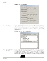
Страница 11: ...click Connection Figure 2 3 and Figure 2 4 will appear The Connection button allows testing of the RS 232 serial port and the AT43DK370 development board connection Prior to going to the Connection m...

Страница 12: ...he Connect to Target but ton to open the selected COM port To verify connectivity between the selected COM port and the AT43DK370 development board click on Test Connectivity with Target and look for...

Страница 13: ...er nal bus the AT43USB370 Host Function Processor 2 Mbytes of flash ROM 2 Mbytes of SRAM USB type A B ports and RS 232 serial port The AT43USB370 connects to the ARM processor through its 32 bit gener...

Страница 14: ...6 MHz crystal clock source is used For debugging purposes an external 48 MHz oscil lator can be used as the clock source to the AT43USB370 by bypassing its internal PLL JP3 was used in DK 1 0 for Rev...

Страница 15: ...sage of USB Clinic in detail Please note since the function calls used in USB Clinic allows the flexibility of user inputs it is the user s responsibility to ensure the inputs are bound to the USB Spe...

Страница 16: ...indow displays all messages and outputs resulting from the execution of USB Clinic commands Click the Clear button to clear the content of the window see Figure 4 2 4 2 2 User Program Output Window Th...

Страница 17: ...K370 firmware revision and its USB Clinic application code revision 4 3 2 Check Device Enumerated The Check Device Enumerated command allows the user to see if the connected tar get USB devices are en...

Страница 18: ...directory Once code download is complete the user has the option of downloading the firmware again without executing the code or executing the downloaded firmware by clicking on Execute Now Resetting...

Страница 19: ...ser will need to select the data size to be read 8 bits 16 bits or 32 bits and then enter the starting address Hex value to read from the target The output displays a maximum of 8 address values for 8...

Страница 20: ...he device address ranges from 1 to 7 and is assigned by the enumeration timing order in which a device is connected to the AT43DK370 Host Figure 4 7 USB Clinic Get Device Descriptor 4 6 2 Get Configur...

Страница 21: ...evice address and the configuration number associated with the target device as inputs The configuration number can be obtained from the bConfigurationValue field of the configuration descrip tors Sin...

Страница 22: ...n 4 7 2 Send ISO Data The Send ISO Data command sends data to a USB device to its Isochronous ISO endpoints The user has to enter the Device Address of the device with the proper ISO Endpoint Packet S...

Страница 23: ...trol The user has to enter the Device Address of the device the Endpoint intended the Packet Type see Table 4 3 Data Toggle see Table 4 4 the number of Retries allowed the number of NAKs allowed the I...

Страница 24: ...the USB Specification Rev 2 0 and to the AT43USB370 Software Development Guide for Host Mode 4 8 2 Clear Port Feature The Clear Port Feature command is used to disable a particular feature on the sele...

Страница 25: ...elected by the Device Address entered The device address ranges from 1 to 7 and is assigned by the enumeration timing order in which a device is connected to the AT43DK370 Host For details about how t...

Страница 26: ...ent Board and the PC This serial connection is NOT active until the Connect to Target button is clicked There is a 1000 character limitation on a single transmission The user will need to break the te...

Страница 27: ...CE mode firmware is used by the In Circuit Emulator that runs code on the AT43DK370 board s SRAM The Download mode firmware also generates an Intel 32 bit Hex file that is used by the USB Clinic that...

Страница 28: ...ew The U SB Proce ssor s ARM Project is prese nted in th e USBP_Library_Rev_x x_Template folder This directory contains the project file USBP_Library mcp USBP_Library mcp is the main project file of A...

Страница 29: ...43USB370 s firmware and all the high low level APIs The USBP_lib h is the header file used for the stand alone library 3 USBP_lib_port This folder contains the processor specific port required to be i...

Страница 30: ...directory is for MSD application code Currently this directory contains all the required routines for MSD applications but it does not contain a sample application code b Application h This is applic...

Страница 31: ...Project Make 5 2 ADS Settings To Make a project the ADS requires to know the format to compile code and how to link its object Those information are stored in a scatter file To assign a scatter file c...

Страница 32: ...e path The DebugRel Settings window is also important for other settings such as first the setting for generating Intel 32 bit Hex format files for USB Clinic download executables To generate the corr...

Страница 33: ...Make process The Image Map file maps each section of the object file to the actual location in memory and the Symbol file maps each variable to the actual memory location These two files provide the...

Страница 34: ...mbol file selection Note The entry point 0x1000 is for ICE In Circuit Emulation mode 5 3 Modifying a Sample Application Go back to the project files see Figure 5 1 on page 2 In USBP_Library mcp there...

Страница 35: ...s is accomplished by calling the UART0XmitStr function with a n at the end of the text string For example add UART0XmitStr Welcome to 370 User IDE This is the Downloaded Version n to the ARM Download...

Страница 36: ...and then select Touch Figure 5 10 Figure 5 10 File Touch Selection The user can then go on the Project Make and that will compile the touched files only Once the output file is created ICE mode axf f...

Страница 37: ...Building Firmware for the AT43DK370 Development Kit AT43DK370 USB Host Function Dev Kit User Guide 5 11 3423C USB 1 04 Figure 5 11 User Program Output Directory...

Страница 38: ...Building Firmware for the AT43DK370 Development Kit 5 12 AT43DK370 USB Host Function Dev Kit User Guide 3423C USB 1 04...

Страница 39: ...o Flash mode to generate the Hex file to be programmed onto the DK flash set and the Download mode to generate the Hex file to be down loaded onto the DK SRAM using USB Clinic The steps to convert bet...

Страница 40: ...t_l file to use the Flash Mode por tion only 4 In ADS go to DebugRel Language Settings ARM Assembler 5 Click on the Predefines tab 6 Add assembly constant FLASH and click Apply see Figure 6 2 Figure 6...

Страница 41: ...anguage Settings ARM Assembler 5 Click on the Predefines tab 6 Delete assembly constant DOWNLOAD and click Apply 7 Go to Language Settings ARM C Compiler Preprocessor 8 Delete C constant DOWNLOAD and...

Страница 42: ...to DebugRel Language Settings ARM Assembler 5 Click on the Predefines tab 6 Delete assembly constant FLASH 7 Go to Language Settings ARM C Compiler Preprocessor 8 Delete C constant FLASH 6 7 Convertin...

Страница 43: ...the board in Flash mode jumper the following pins on the headers a In JP4 jumper together FLASH_CS and nRCS 0 b In JP4 jumper together SRAM_CS and nRCS 1 c In JP7 jumper together pin 1 2 2 The project...

Страница 44: ...record leave that one in Note For the DOWNLOAD mode hex file taking out the 02000 lines is not required 5 Use Hex2Vcx exe to split this file into 4 hex files for each flash The Hex2Vcx exe can be fou...

Страница 45: ...form in the C Program Files ATMEL USB AT43DK370 directory Alternatively fill out an online support form available in the Product Section of the Atmel web site at http www atmel com Please make sure t...

Страница 46: ...Technical Support 8 2 AT43DK370 USB Host Function Dev Kit User Guide 3423C USB 1 04...

Страница 47: ...Digikey PCC1812CT ND 4 2 C17 C22 1000 pF Ceramic 0805 Panasonic ECJ 2VC1H102J Digikey PCC102CGCT ND 5 3 C18 C23 C25 33 pF Ceramic 0805 Panasonic ECJ 2VC1H330J Digikey PCC330CGCT ND 6 4 C44 C45 C46 C4...

Страница 48: ...J FC1R2JF Digikey PCD1229CT ND Semiconductor 28 1 U1 USB Host Processor Atmel AT43USB370 29 1 U8 Triple Voltage Regulator Maxim MAX1702BEGX 30 1 U9 ARM Processor Samsung S3C4510 31 1 U10 RS 232 Line T...

Страница 49: ...entary Push Button Switch E Switch 520 02 RED Digikey EG1415 ND Second Level Components Stuffing 48 4 U4 U5 U6 U7 ROM 256K x 8 90 ns Atmel AT49LV002 90PC 49 1 U17 PAL 16v8 PLCC 10 ns Atmel ATF16LV8C 1...

Страница 50: ...Appendices 9 4 AT43DK370 USB Host Function Dev Kit User Guide 3423C USB 1 04 Figure 9 1 ARM Schematic...

Страница 51: ...Appendices AT43DK370 USB Host Function Dev Kit User Guide 9 5 3423C USB 1 04 Figure 9 2 AT43USB370 Schematic...

Страница 52: ...Appendices 9 6 AT43DK370 USB Host Function Dev Kit User Guide 3423C USB 1 04 Figure 9 3 SRAM Schematic...

Страница 53: ...Appendices AT43DK370 USB Host Function Dev Kit User Guide 9 7 3423C USB 1 04 Figure 9 4 FLASH Schematic...

Страница 54: ...Appendices 9 8 AT43DK370 USB Host Function Dev Kit User Guide 3423C USB 1 04 Figure 9 5 Serial Port Connectors and USB Power Schematic...

Страница 55: ...Appendices AT43DK370 USB Host Function Dev Kit User Guide 9 9 3423C USB 1 04 Figure 9 6 Power Supply Schematic...

Страница 56: ...Appendices 9 10 AT43DK370 USB Host Function Dev Kit User Guide 3423C USB 1 04...

Страница 57: ...way San Jose CA 95131 USA Tel 1 408 441 0311 Fax 1 408 436 4314 Microcontrollers 2325 Orchard Parkway San Jose CA 95131 USA Tel 1 408 441 0311 Fax 1 408 436 4314 La Chantrerie BP 70602 44306 Nantes Ce...

Отзывы: