AT43DK370 USB Host/Function Dev. Kit User Guide
7-1
3423C–USB–1/04
Section 7
Generating Hex Files for Flash Mode
in the AT43USB370 Development
Board with ADS
7.1
Introduction
This section gives directions on generating hex file for Flash mode in the AT43USB370
Development Board with ADS.
7.2
Procedure
1.
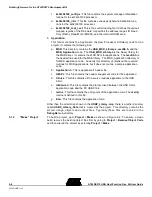
To put the board in Flash mode jumper the following pins on the headers:
a.
In JP4, jumper together FLASH_CS and nRCS<0>
b.
In JP4, jumper together SRAM_CS and nRCS<1>
c.
In JP7, jumper together pin 1-2
2.
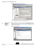
The project entry point must be changed from to 0x0. To change the entry point,
go to DebugRel > ARM Linker > Options > Image Entry Point column and set
it to 0x0.
3.
Add the Predefine constant
FLASH
in the ARM Assembler and Compiler (see
4.
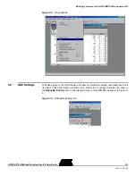
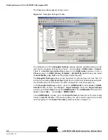
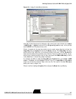
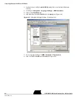
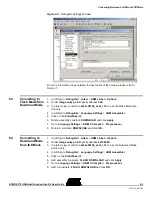
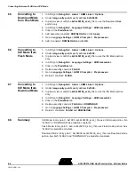
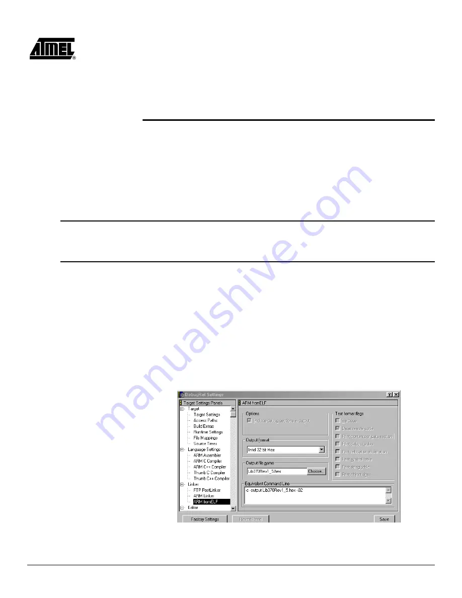
To create a Hex file do the following:
Figure 7-1.
Post-linker Setting: ARM fromELF
Содержание AT43DK370
Страница 1: ...AT43DK370 USB Host Function Development Kit User Guide for Revision 1 3...
Страница 2: ......
Страница 6: ...Table of Contents iv AT43DK370 USB Host Function Dev Kit User Guide 3423C USB 1 04...
Страница 8: ...Introduction 1 2 AT43DK370 USB Host Function Dev Kit User Guide 3423C USB 1 04...
Страница 46: ...Technical Support 8 2 AT43DK370 USB Host Function Dev Kit User Guide 3423C USB 1 04...
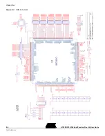
Страница 50: ...Appendices 9 4 AT43DK370 USB Host Function Dev Kit User Guide 3423C USB 1 04 Figure 9 1 ARM Schematic...
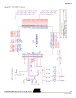
Страница 51: ...Appendices AT43DK370 USB Host Function Dev Kit User Guide 9 5 3423C USB 1 04 Figure 9 2 AT43USB370 Schematic...
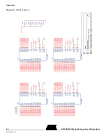
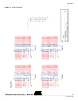
Страница 52: ...Appendices 9 6 AT43DK370 USB Host Function Dev Kit User Guide 3423C USB 1 04 Figure 9 3 SRAM Schematic...
Страница 53: ...Appendices AT43DK370 USB Host Function Dev Kit User Guide 9 7 3423C USB 1 04 Figure 9 4 FLASH Schematic...
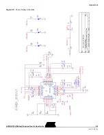
Страница 55: ...Appendices AT43DK370 USB Host Function Dev Kit User Guide 9 9 3423C USB 1 04 Figure 9 6 Power Supply Schematic...
Страница 56: ...Appendices 9 10 AT43DK370 USB Host Function Dev Kit User Guide 3423C USB 1 04...


