2
Installation Guide
AT-HDVS-SC-RX
FW
AT-HDVS-SC-RX
DC 24V
1
C1 COM C2
2
HDMI OUT
INPUT
RX
TX
TX
RX
2
1
R
L
RS-232
AUDIO OUT
RELAY
ENTER
INPUT
MENU
<
>
AT-HDVS-SC-RX
PWR
LINK
INPUT
1
2
LAN
4K SCALER
FW
AT-HDVS-SC-RX
DC 24V
1
C1 COM C2
2
HDMI OUT
INPUT
RX
TX
TX
RX
2
1
R
L
RS-232
AUDIO OUT
RELAY
ENTER
INPUT
MENU
<
>
AT-HDVS-SC-RX
PWR
LINK
INPUT
1
2
LAN
4K SCALER
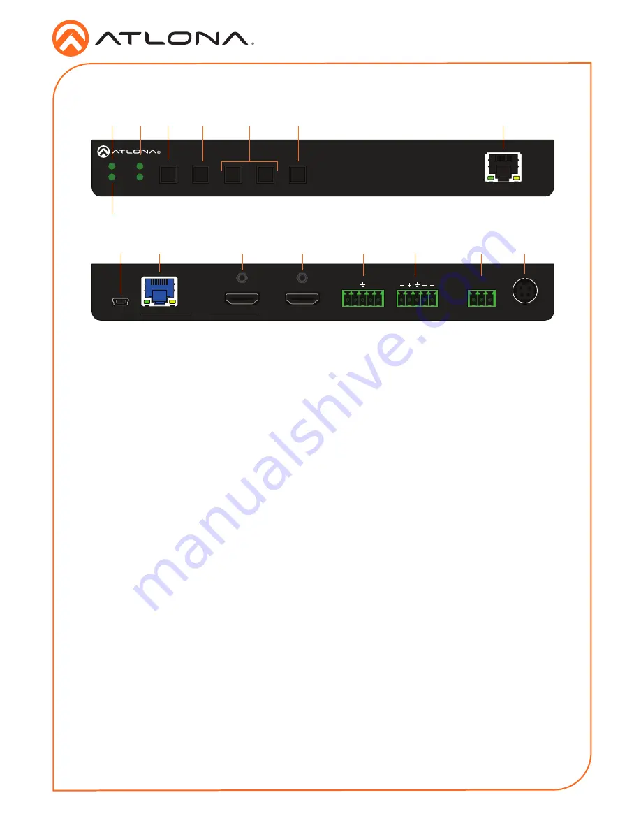
Panel Description
1
PWR
This LED indicator glows solid green when
the unit is powered. When set to standby
mode, this LED indicator glows solid
amber.
2
LINK
This LED indicator displays the link status.
3
INPUT 1 / 2
These LED indicators display the currently
selected input. The active input will be
indicated by a solid green LED.
4
MENU
Press this button to display the built-in
menu system.
5
ENTER
Press this button to confirm the
highlighted selection in the menu system.
6
UP / DOWN
Press these buttons to highlight the
desired options in the menu system.
7
INPUT
Press and release this button to toggle
between
INPUT 1
and
INPUT 2
. The
INPUT 1 and INPUT 2 LED indicators will
toggle, based on the selected input.
8
LAN
Connect an Ethernet cable from this port
to the Local Area Network.
9
FW
Connect a mini USB cable to this port to
update the firmware.
10 HDBaseT Input
Connect a transmitter, such as the AT-
UHD-PRO3-44M, to this port using an
Ethernet cable.
11 HDMI Input
Connect a UHD/HD source to this port
using an HDMI cable.
12 HDMI OUT
Connect an HDMI cable from this port to a
display or other sink device.
13 RS-232
Connect the included 5-pin captive screw
block to this port.
14 AUDIO OUT
Connect the included 5-pin captive
screw block to this port. Refer to
Audio
Output Connector (page 3)
for wiring
information.
15 RELAY
Slide this switch to set the correct speaker
impedance or voltage setting.
16 DC 24V
Connect the included 24 V DC locking
power supply to this power receptacle.
Front
Rear
2
1
9
10
11
12
13
14
15
16
3
4
5
6
7
8
Содержание AT-HDVS-SC-RX
Страница 11: ...11 Installation Guide AT HDVS SC RX Notes ...

