background image

4

'& ! ' &

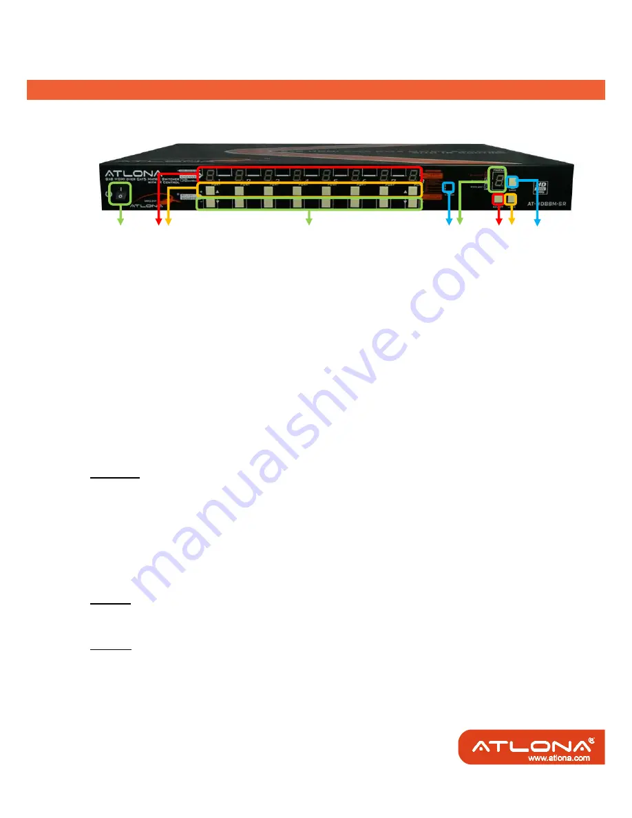
Front Panel of AT-HD88M-S  

1.  Power on/off switch 

2. 

PORT 1-7

: LED display to show which input source is playing on which port 

3. '

' buttons: press the buttons for selecting input source in ascending sequence 

4. '

' buttons: press the buttons for selecting input source in descending sequence 

5. 

IR SENSOR

: receiving IR commands from the IR remote 

6. 

PRESET PROFILES

: LED display to show preset profiles and other built-in modes  

7. 

SELECT

: press the button for preset profiles (1-8) and mode selection (E, L, H) in rotary order 

8. 

LOAD

: press the button to load selected preset profile 

9. 

SAVE

: press the button to save current channel mapping to selected preset profile 


Mode  Selection  (1, 2, 3, 4, 5, 6, 7, 8, E, H, L, 1, 2, .....) 

Mode 1-8: Preset Profiles 

The matrix allows 8 sets of channel mapping configuration saved as preset profiles for later use. 

Save current configuration: 

push the 

SELECT

 button to assign the preset profile (1-8) then press the 

SAVE

 button to save the current channel mapping configuration into this designated preset profile. 

Load previously saved configuration: 

push the 

SELECT

 button to desired preset profile (1-8) then press 

the 

LOAD

 button to restore the previously saved channel mapping configuration from the 

designated preset profile. 

Mode E: EDID Learning Mode 

Please find the detail in the following section for operation in EDID Learning mode. 

Mode H: Panel Hold and Unhold 

Hold:

 push 

SELECT

 button until the 

PRESET PROFILES

 shows 

“H”

 and keep pressing the 

SELECT

button for 3 seconds, then all of the buttons on the matrix front panel will be ineffective automatically. 

Unhold: 

when the LED display of 

PRESET PROFILES

 shows 

“H”

, keep pressing the 

SELECT 

button for 

3 seconds until the 

PRESET PROFILES

 shows 

“1”

 to unhold all of the buttons on the front panel.

1

2 3

4

5 6

7 8

9

Содержание AT-HD88M-SR

Страница 1: ... ...

Страница 2: ...ents 3 3 Panel Description 4 4 DIP Switch 7 5 IR Pass through 9 6 Hardware Installation 11 7 Performance Guide 11 8 Channel Control 12 9 EDID Learning 17 10 IR Direct Code 18 11 Safety Information 20 12 Warranty 21 13 Atlona Product Registration 22 ...

Страница 3: ...t the same time Through low cost Cat 5 5e 6 cables not only high quality video and audio can be transmitted to the display sites but also users can switch among eight HDMI sources using the push in button or remote control With single power design at the source site each remote module is easily installed without power supply Furthermore the built in IR extension function let users can control the ...

Страница 4: ...ling local HDMI sources such as DVD and TiVo by IR extender through control path at remote receiver Allows to control main matrix center through control line at remote receiver Extends video signal up to 35m 115 feet over CAT5e at 1080p and likely longer with better HDMI source device such as PS3 and better quality solid CAT6 cable Easy installation with rack mounting and wall mounting designs for...

Страница 5: ...IR blaster IR Main IR control on all source devices IR PASS THROUGH1 8 IR control on individual source device Earphone jack for IR receiver IR RECEIVER Receives IR commands from remote control DIP switch SW1 SW8 2 pin for EDID audio mode SW Main 4 pin for operation firmware update Mechanical AT HD88M S AT HD88M R Enclosure Metal enclosure Dimensions L x W x H 290 x 440 x 44mm 11 4 x 1 5 x 1 7 90 x...

Страница 6: ...as preset profiles for later use Save current configuration push the SELECT button to assign the preset profile 1 8 then press the SAVE button to save the current channel mapping configuration into this designated preset profile Load previously saved configuration push the SELECT button to desired preset profile 1 8 then press the LOAD button to restore the previously saved channel mapping configu...

Страница 7: ...unctions Rear Panel of AT HD88M S 10 AC Power 100 250V 50 60Hz 11 RS 232 RS 232 control port 12 USB USB control port 13 SW Main 4 pin DIP switch see DIP Switch section in p 8 14 SW 1 SW 8 2 pin DIP switch see DIP Switch section in p 8 15 INPUT 1 INPUT 8 HDMI inputs that connect to HDMI source devices 16 IR PASS THROUGH 1 8 3 5mm IR blaster socket for individual HDMI source control 17 OUPUT PORT 1 ...

Страница 8: ...r 6 Signal Level 0 7 adjust the 8 level equalization control to the received HDMI signals The HDMI signal level varies from 0 strongest to 7 weakest for respective transmission length from longest possible range to short distance It is recommended to switch from 7 to 0 to find the optimal visual experience 7 HDMI OUTPUT connect to HDTV with a HDMI cable 8 IR RECEIVER plug in the IR receiver The AT...

Страница 9: ...among different kinds of HDMI sources and displays If you cannot get the audio and or video output normally at the system installation please change the DIP switch setting to default mode or even safe mode to verify the functionality of the device 5 To learn the EDID of HDMI display for respective HDMI source devices please see the EDID Learning section in the next page for more detail information...

Страница 10: ...pdate WARNING Firmware update only can be done via RS 232 port and connection to PC set at COM1 1 Power off the AT HD88M S Execute the firmware update program on your PC via COM1 port connection to the RS 232 port of the AT HD88M S 2 Set the pin 1 of SW Main at ON ª for firmware update mode 3 Set pin 2 and pin 3 at respective positions to assign which Block to be updated 4 Power on the AT HD88M S ...

Страница 11: ...remote receivers to all of the HDMI sources IR PASS THROUGH 1 8 IR blaster connected here can only transmit IR command signals from the remote receivers that are setting at respective input channel from 1 to 8 AT HD88M R IR RECEIVER IR receiver connected here can receive all IR command signals from the IR remote controls of AT HD88M SR and all other HDMI source devices ...

Страница 12: ...f necessary for replacement use Supported IR Data Format Data Format Suitable Not Recommended NEC 5 RC5 5 TOSHIBA MICOM CODE 5 GRUNDIG CODE 5 SONY 12 BIT CODE 5 SONY 15 BIT CODE 5 SONY 20 BIT CODE 5 RCA CODE 5 RCM CODE 5 MATSUSHITA CODE 5 MITSUBISHI CODE 5 ZENITH CODE 5 JVC CODE 5 M50560 001P 5 MN6125H 5 MN6125L 5 MN6014_C5D7 5 MN6014 C6D6 5 MC14457P 5 LC7464 AHEA 5 GEMINI_CM 5 ...

Страница 13: ...all HDMI sources 7 Power on the AT HD88M S AT HD88M R as receiver unit 1 Connect each HDMI output to HDMI displays 2 Connect the A V SIGNAL port on the AT HD88M R to the A V SIGNAL port on the AT HD88M S 3 Connect the CHANNEL CONTROL port on the AT HD88M R to the CHANNEL CONTROL port on the AT HD88M S 4 Connect IR receiver and place the IR receiver at the appropriate position that can receive the ...

Страница 14: ... the lower right corner lights up to indicate that the matrix receives the IR command Note F1 HDMI output port 1 F2 HDMI output port 2 F3 HDMI output port 3 F4 HDMI output port 4 F5 HDMI output port 5 F6 HDMI output port 6 Enter HDMI output port 7 Exit HDMI output port 8 Up S Switch output port in ascending order Down T Switch output port in descending order b Use left W or right X button to selec...

Страница 15: ...he number of selected input source channel Or you can use up S and down T button to enter IR control mode and select the input channel in ascending and descending order respectively Note F1 HDMI input source 1 F2 HDMI input source 2 F3 HDMI input source 3 F4 HDMI input source 4 F5 HDMI input source 5 F6 HDMI input source 6 Enter HDMI input source 7 Exit HDMI input source 8 Up S Switch source in as...

Страница 16: ...tton the machine will scan the all com port and show them Select the RS 232 serial port connected to the machine And set device ID 255 is for all device Only the same device ID or 255 can get the command you sent Press OK to get the new status from the machine you select Input Source indicator Output port Status Indicator ...

Страница 17: ... the same source Unselect All Output Release output selection Select Input1 8 Output Select Input Source Then select the output port icon For example Select input source 1 Then select output port one and two The video and audio will be send to port one and two 6 Fast Select button Press Fast select button Quick setting Input one Output Port one Input two Output Port two Press Fast select pull down...

Страница 18: ...nput4 D2 Output D select Input2 F8 Output F select Input8 A5 Output A select Input5 D3 Output D select Input3 G1 Output G select Input1 A6 Output A select Input6 D4 Output D select Input4 G2 Output G select Input2 A7 Output A select Input7 D5 Output D select Input5 G3 Output G select Input3 A8 Output A select Input8 D6 Output D select Input6 G4 Output G select Input4 B1 Output B select Input1 D7 O...

Страница 19: ...witch Method B Using Front Panel 1 Push the SELECT button until the LED display of PRESET PROFILES shows E to enter the EDID Learning Mode 2 Press Up button or Down button to choose which output display s EDID will be learned by each input port and the number of the chosen output display will be shown on the LED display 3 Each input port of the matrix can learn the same or differently chosen displ...

Страница 20: ...urce 0x05 Source LEFT 0x05 OUTPORT UPPER 0x16 OUTPORT DOWN 0x0D Custom Code IR3 0x12 0x21 Custom Code 0x12 0x21 Output Port 1 Output Port 2 Output Port 3 Output Port 4 Output Port 5 Output Port 6 Output Port 7 Output Port 8 Source 1 0xA1 0xB1 0xC1 0xD1 0xE1 0xF1 0x11 0x21 Source 2 0xA2 0xB2 0xC2 0xD2 0xE2 0xF2 0x12 0x22 Source 3 0xA3 0xB3 0xC3 0xD3 0xE3 0xF3 0x13 0x23 Source 4 0xA4 0xB4 0xC4 0xD4 ...

Страница 21: ...xCC 0xDC 0xEC 0xFC 0x1C 0x2C Source 4 0xAB 0xBB 0xCB 0xDB 0xEB 0xFB 0x1B 0x2B Source 5 0xAA 0xBA 0xCA 0xDA 0xEA 0xFA 0x1A 0x2A Source 6 0xA9 0xB9 0xC9 0xD9 0xE9 0xF9 0x19 0x29 Source 7 0xA8 0xB8 0xC8 0xD8 0xE8 0xF8 0x18 0x28 Source 8 0xA7 0xB7 0xC7 0xD7 0xE7 0xF7 0x17 0x27 Note Using terminal to set Custom Code Example Set custom code from 0x01 0xEE to 0x13 0x31 IR4 command using RS 232 terminal c...

Страница 22: ... device and plug it back in Protect and route power cords so they will not be stepped on or pinched by anything placed on or against them Be especially careful of plug ins or cord exit points from this product Avoid excessive humidity sudden temperature changes or temperature extremes Keep this product away from wet locations such as bathtubs sinks laundries wet basements and swimming pools Use on...

Страница 23: ... 3 NO OTHER WARRANTIES TO THE MAXIMUM EXTENT PERMITTED BY APPLICABLE LAW ATLONA TECHNOLOGIES AND ITS SUPPLIERS DISCLAIM ALL OTHER WARRANTIES EITHER EXPRESS OR IMPLIED INCLUDING BUT NOT LIMITED TO IMPLIED WARRANTIES OF MERCHANTABILITY AND FITNESS FOR A PARTICULAR PURPOSE WITH REGARD TO THE PRODUCT AND ANY RELATED WRITTEN MATERIALS THIS LIMITED WARRANTY GIVES CUSTOMER SPECIFIC LEGAL RIGHTS CUSTOMER ...

Страница 24: ...ct is lost or stolen and helps ensure you ll receive notification of performance issues and firm ware updates At Atlona we respect and protect your privacy and assure you that your registration information is completely secure Of course Atlona product registration is totally voluntary and failure to register will not diminish your limited warranty rights To register go to www atlona com registrati...

Отзывы: