Page 52 / 56
00BNO9132-#
VARMAX TWIN -
Installation, Use and Maintenance
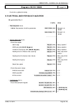
E. ELECTRICAL AND HYDRAULIC VALIDATION
On generator No. 1
Line No.
Value
• Flow diagnostic
menu
Validate the presence of all the generators
Gener 1 status (8100)
Released / not
released
Gener 2 status (8101)
Released / not
released
...............................
• Inputs/outputs test
menu
Check the outputs
Alarm relay
Relay test (7700)
Relay output QX1
Isolating valve Q1.1
Relay test (7700)
Relay output QX3
All the extension module relays
Relay test (7700)
Relay output QX2...
module ...
Reset the outputs
Relay test (7700)
No test
Check the sensor values
External sensor B9
External T° B9 (7730)
in °C
DHW sensor B3
(VX212 diagram)
DHW temperature B3/B38 (7750)
in °C
TWIN B10 output sensor
BX2 sensor T° (7821)
in °C
B1 fl ow sensor
Temperature sensor BX21 module 1 (7830)
in °C
Diagrams: VX202 / VX212
page 7 / 9
Line No.
Value
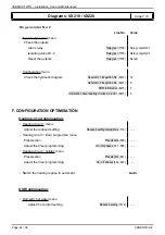
If 4th heating circuit present:
• Adjust the heating circuit
Heating circuit 1
menu
Adjust the comfort setting
Comfort setting temperature (710)
- - -
Adjust the curve slope
Heating curve slope (720)
- - -
• Switch the heating regime to permanent comfort
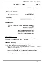
• Make sure that the communication cable is fully connected between the 2 generators (
!
respect
the polarity).
• Switch off and back on again generator 2. If the communication has been correctly established,
the clock is updated correctly.
Содержание Varmax Twin
Страница 2: ......


