Edition: 02 / 2015
Page 49 / 56
VARMAX TWIN -
Installation, Use and Maintenance
AVS75
QX21
No.
QX22
No.
QX23
BX21
Gnd
BX22
Gnd
H2
Gnd
}
}
}
}
Module 1
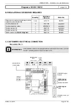
Regulated circuit output sensor
B1.2
Heating circuit No. 4 mixer
valve Y1.2/Y2.2
Heating circuit No. 4
circulator Q2.2
(for the heating circuit in dotted lines
on the hydraulic diagrams)
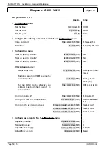
D. SPECIFIC START-UP PROCEDURE
Make the accessories' electrical connections.
Start up the generator on its own.
Carry out the adjustments below.
!
IMPORTANT:
Con
fi
gure the switches on the AVS75 extension modules.
L
N Y1
N
Y2 L
N L
N L
N
QX2
QX3
QX1
AUX2
AUX1
230 VAC 50 Hz
power supply
}
}
DB MB
}
Alarm
relay
Isolating
valve Q1.2
LPB bus
Diagrams: VX202 / VX212
page 4 / 9
BX2
Gnd
BX3
Gnd
B3
Gnd
B9
Gnd
H1
Gnd
H5
Gnd
}
Isolating valve end
of run
Содержание Varmax Twin
Страница 2: ......


