


Technical Manual & Parts Lists
16
off-loading the panel to the rear of the machine and helping move the next panel to the sewing head. Tap
the Conveyor Pedal to stop the conveyor.
Sew Head Corner Speed (#10) controls the speed of sewing around the corners. Adjust as needed to get
a flat corner sew and to be synchronous with the corner rotation speed.
Sew Corner Stitch Count (#11) controls the number of stitches sewn during corner rotation. Adjust so
the sewing stops at the about the same time as the corner has finished rotating. Increasing or decreasing
can affect the shape of the corner. Adjust as needed to get a uniformly shaped corner.
Edge Guide Stop Count (See LAST CORNER ADJUSTMENTS note #3 above).
Flange Overlap Stitch Count (See LAST CORNER ADJUSTMENTS note #2 above).
Law Tag Enable Side 2 (#14) turns on a stop function for inserting a label on side two (short side after
first corner). Location is controlled by Law Tag Stop Count Side 2 (#17).
Label 2 Enable Side 3 (#15) turns on a stop function for inserting a label on side three (long side after
second corner). Location is controlled by Label 2 Stop Count Side 3 (#18).
Stitch Condense Enable (#16) turns on or off stitch condensing in the corners. When on, it shortens the
feed stitch length in the corner. It is adjustable on the left side of the head under the cloth plate. Set as
needed to achieve uniform corner sewing. Used in conjunction with the Sew Corner Stitch Count.
Thread Detector Enables (#19, 20, 22, 23, and 26) Turns on and off the Thread Break Detectors.
Thread Detector Enable Delay (#21) is a time delay after start of sewing on straight side of panel before
the Thread Break Detectors become active. This delay allows the sewing head to get to speed before the
Thread Break Detectors start monitoring the thread movement. Thread Break Detectors are not active
during the corner sewing.
Thread Tension Stitch Count (#24) is a stitch count from the trailing edge eye until the safety stitch
needle tension opens at the end of the panel to let the safety stitch thread chain off up to the thread
cutter. Set so the tension opens a few stitches before the end of the panel. If the safety stitch needle is
not chaining off, reduce this setting.
Panel Jam Detect Enable (#25) turns on and off the Panel Jam Detector function. See Jam Detect Set
Distance (#37) below.
Minimum Air Pressure (#27) sets the minimum operation pressure at which the machine will be allowed
to operate.
Actual Stitch Length (#28) is the same setting also on the Operator screen. This MUST be set to indicate
the actual stitches-per-inch that the machine is sewing and is used by the machine to control the corner
sewing, conveyor synchronization, flange overlap, and flange cut position. The resolution is in tenths of
an inch – so 6.0 indicates 6 stitches per inch, 6.5 would be 6-1/2 stitches per inch, for example.
Corner Stop Count (#29-35) controls the corner stopping position prior to starting the corner turn. It is
adjusted so that the trim margin of the edge cutter is the same coming out of the corner as it was going
into the corner. Each counter is individually settable based on the Actual Stitch Count setting. So, if you
Содержание 1317A
Страница 2: ...Technical Manual Parts Lists 1 ...
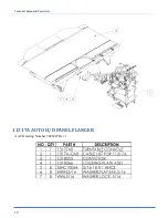
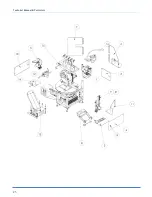
Страница 24: ...Technical Manual Parts Lists 19 11317A AUTO H D PANEL FLANGER AAC Drawing Number 9005447 Rev 1 ...
Страница 28: ...Technical Manual Parts Lists 23 ...
Страница 30: ...Technical Manual Parts Lists 25 ...
Страница 32: ...Technical Manual Parts Lists 27 ...
Страница 34: ...Technical Manual Parts Lists 29 ...
Страница 36: ...Technical Manual Parts Lists 31 ...
Страница 39: ...Technical Manual Parts Lists 34 ...
Страница 40: ...Technical Manual Parts Lists 35 ...
Страница 42: ...Technical Manual Parts Lists 37 ...
Страница 44: ...Technical Manual Parts Lists 39 ...
Страница 48: ...Technical Manual Parts Lists 43 ...
Страница 50: ...Technical Manual Parts Lists 45 ...
Страница 51: ...Technical Manual Parts Lists 46 1318112 1 CONTROL PANEL AAC Drawing Number 1318112 Rev 2 ...
Страница 52: ...Technical Manual Parts Lists 47 ...
Страница 55: ...Technical Manual Parts Lists 50 ...
Страница 56: ...Technical Manual Parts Lists 51 ...
Страница 60: ...Technical Manual Parts Lists 55 ...
Страница 63: ...Technical Manual Parts Lists 58 ...
Страница 64: ...Technical Manual Parts Lists 59 ...
Страница 71: ...Technical Manual Parts Lists 66 ...
Страница 72: ...Technical Manual Parts Lists 67 ...
Страница 79: ...Technical Manual Parts Lists 74 ...
Страница 81: ...Technical Manual Parts Lists 76 ...
Страница 83: ...Technical Manual Parts Lists 78 ...
Страница 85: ...Technical Manual Parts Lists 80 1318356 CONVEYOR SUB ASSY 2 AAC Drawing Number 1318356 Rev 0 ...
Страница 88: ...Technical Manual Parts Lists 83 ...
Страница 89: ...Technical Manual Parts Lists 84 ...
Страница 92: ...Technical Manual Parts Lists 87 ...
Страница 93: ...Technical Manual Parts Lists 88 ...
Страница 98: ...Technical Manual Parts Lists 93 ...
Страница 100: ...Technical Manual Parts Lists 95 ...
Страница 102: ...Technical Manual Parts Lists 97 ...
Страница 104: ...Technical Manual Parts Lists 99 1317A PSM PROGRAM SETTINGS MAP ...
Страница 105: ...Technical Manual Parts Lists 100 1317A WD WIRNG DIAGRAM CNTRL PNL ...
Страница 106: ...Technical Manual Parts Lists 101 1317A PD PNEUMATIC DIAGRAM 1317A ...
Страница 107: ...Technical Manual Parts Lists 102 ...