18
Assembly
Please note the attached assembly instruction
sheet!
Assembling the device
►
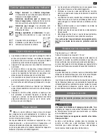
Fold the dry wall sander and guide the locking screw
(9) into the slot, as shown, and press down the locking lever
(10).
Correct the screw length if the locking screw (9) cannot
be guided into the slot.
►
Loosen the counter nut (a) and screw the locking
screw in/out.
►
Retighten the locking nut.
The dry wall sander is only properly locked when
the locking lever is pressed all the way down.
Sanding disc
►
Place the sanding disc (3) on the sanding pad (2) so
that the holes of the sanding disc are aligned with the holes
on the sanding pad.
When using dust extraction be sure to only use
sanding discs with holes since they improve dust ex-
traction.
►
Press down the sanding disc.
Telescopic handle
Use the telescopic handle (14) to sand high walls or
ceilings.
►
Press the locking button (13) and adjust the tele-
scopic handle to the desired length.
►
Release the locking button.
Make sure that it engages.
Connecting a dust extraction
Always connect the dry wall sander to dust extraction
for health reasons.
►
Guide the extraction hose (2) into the connection
piece (18) and secure it against falling out by twisting it.
►
Connect the extraction hose with the dust extraction.
Use one of the two adapters if the devices cannot
be connected.
Adapter (19) Ø 40 mm
Adapter (20) Ø 47 mm
►
Push the adapter, as shown, onto the extraction hose (21)
using a screwdriver.
Start-up
Do not use any device where the switch can not be
switched on and off. Damaged switches must be repaired
or replaced immediately by the customer service.
Check that the machine is completely and correctly assem-
bled.
Before each use, check
Connection cables for defects (cracks, cuts, etc.).
Do not use any defective cables.
there are no damages at the machine
(see "safe working")
that the sanding disc, sanding pad and brush ring seg-
ment are firmly seated
Mains connection
Compare the voltage given on the machine model plate e.g.
220-240 V with the mains voltage and connect the machine
to the relevant and properly earthed plug.
Alternating current motor:
Use a shockproof plug, mains voltage 220-240 V with residual
current circuit breaker 30 mA.
Use the connection or extension cable according to IEC 60245
(H 07 RN-F) with a core cross-profile section of at least
1.5 mm
2
for cable lengths
up to
25 m
2.5 mm
2
for cable lengths
over
25 m
Switching on
Do not use any device where the switch can not be
switched on and off. Damaged switches must be repaired
or replaced immediately by the customer service.
When using dust extraction, switch this unit on first.
Start the machine at the lowest rotational speed (setting 1)
►
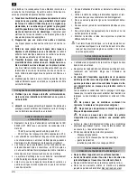
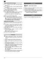
First press the trip switch (11a) at the back of the
ON-OFF switch (11) and then slide the switch forward.
The switch is locked.
You do not need to keep the switch depressed.
Switching off
►
Press the trip switch (11a) at the back of the ON-
OFF switch (11).
The lock on the switch releases.
The sanding pad runs down after the machine is
turned off.
Wait therefore until the sanding pad has
stopped before putting down or restarting the device.


