8
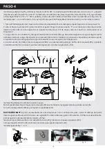
Installing the Pedals (44 and 45) and Link Arms (07R and 07L)
The Left Pedal (44) is marked with an “L” and the Right Pedal (45) is marked with an “R”. So are the left and right Link
Arms (07R and 07L) which are also labeled with “R” and “L”. These Pedals and Link Arms needs to be assembled as
described in Figure 4 with Diagrams 1 to 4 correctly. It is very important that each Pedal and Link Arm is fixed on the
correct sides.
1. Take the Left Pedal (44). Slide the Pedal Bearing (29) on to the pedal stem of the Left Pedal as shown.
2. Rotate the Link Arm (07L) to meet the Pedal. Bring the “C” open slot on the Link Arm up from the bottom to hook
on the Two Step Bearing (29) from under as shown below in Diagram 2 below.
3. Then insert the Metal Bushing (30) through the Pedal Stem. Ensure the Metal Bushing is well inserted through
the holes of the Washer and “C” open slot of the Link Arm. Then fix the Pedal onto the Crank (09) as shown below.
The Left Pedal tightens anti-clockwise onto the Crank as shown on Diagram 3.
4. Then screw on the Lock Nut (28L) onto the Pedal Stem, from behind the Crank (09) and tighten it in the counter-
clockwise screwing direction as shown in Diagram 4 with the Wrench (53) and (54).
STEP 4
4 4 ( L )
2 9
0 7 L
2 3
3 0
0 9
2 8 L
2 9
0 7 L
5 3
4 5 ( R)
2 8 ( R)
5 4
Install the Right Pedal (45) in the same manner.
Note: The Right Pedal locks onto the Crank (09) in the clockwise direction when screwing into it.
The Lock Nut (28R) is for tightening the Right Pedal.
VERY IMPORTANT
: Please follow the depictions or Diagrams 1 to 4 below, step by step. The Pedal Stem must be
secured tightly, the Lock Nut must be secured tightly too. Check occasionally to ensure it is always secure and firm
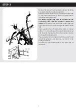
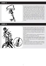
Insert Lock Clip (56) into steel bushing (29) and Left Connection Bar (07L).
Attach the right pedal (45) in the same way as left pedal(44).
Install following fig. 1 - 2 - 3.
56
29
44
07L
fig. 1
fig. 2
fig. 3


