www.atestgaz.pl
7. Turn the control unit power on.
8. Set up Extension Module parameters as required (see section 5.9).
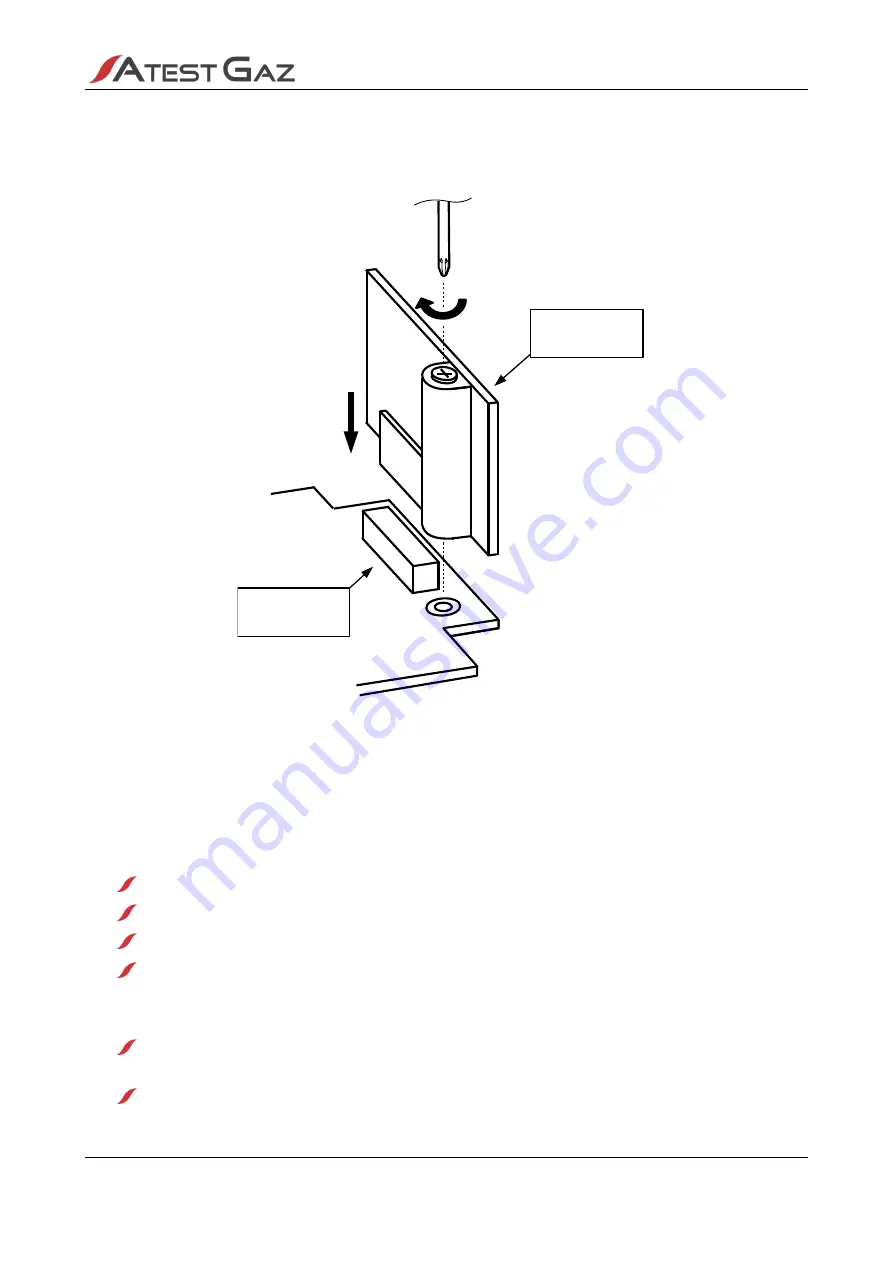
Figure 10: Installing the Extension Module
For a detailed Extension Module drawing, connection description and functionality settings, see the
Extension Module instructions – see appendix: [2] and [3].
5
User's interface
User’s interface includes:
LCD display that provides measurement data, diagnostic information, all detector statuses,
navigation keyboard allowing the user to browse the unit menu in an easy and intuitive way,
built-in buzzer triggered when any malfunction requiring operator intervention is detected,
System Visual Indicator that allows the user to access the system “at a glance”, even from
a distance.
Operation principle
During standard operation (no risks or special statuses) it is System Visual Indicator that remains
enabled – only the green LED “MONITORING” is on.
If any gas alarms and/or special statuses appear, the built-in buzzer warns the operator who can
easily assess the new system event by verifying four – colour System Visual Indicator.
p. 15|38
User's Manual: POD-026-ENG R17
I.
II.
Extension
module port
Extension
module
Содержание PW-072-A
Страница 1: ...POD 026 ENG R17 User Manual Control Unit Sigma Control L Product code PW 072 A...
Страница 59: ......


