9
ATE FB 15 Operating Manual
Filling, bleeding the brake
system, replacing mineral
hydraulic oil
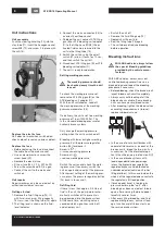
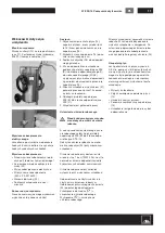
1. Remove the fluid reservoir cap
2. Extract the fluid completely from the
fluid reservoir using the ATE suction
bottle (A)
3. Connect the ATE filling gun (B) to the
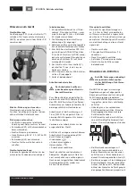
filling hose (07/08); switch the unit on
4. Completely fill the fluid reservoir with
new fluid; disconnect the ATE filling
gun (B)
5. Fit the suitable ATE bleeding unit
adapter (C) airtight to the fluid reservoir
6. Connect the filling hose (07/08) to the
ATE bleeding unit adapter (C)
7. Insert the hose of the ATE collection
bottle (D) onto a bleed valve; open the
bleed valve until fresh, clear,
bubble-free fluid flows out
8. Repeat the procedure on each of the
bleed valves with the collection bottle
fitted
9. When fitting a new tandem main
cylinder: Press the brake pedal down
as far as it will go several times while
the fluid is flowing out in order to re-
move the air bubbles completely from
the tandem main cylinder
10. End of bleeding; switch the unit off;
remove the filling hose (07/08) first,
then the ATE bleeding unit adapter (C)
11. Correct the fluid to the MAX mark
using the ATE suction bottle (A)
12. Check the bleeding hole of the origi-
nal fluid reservoir cap for permeability
and then fit it
Special bleeding
Special bleeding is not permitted
on vehicles with ABS
1. Bleeding in special cases via bleed
valve (from bottom to top). This meth-
od must be used when bleeding at
more than 2 bar (200,000 Pa).
2. Extract the fluid completely from the
fluid reservoir using ATE suction bottle
(A)
3. Connect the ATE filling gun (B) to the
filling hose (07/08); switch the unit on
4. Fill the fluid reservoir up to the MAX
mark; disconnect the ATE filling gun (B)
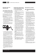
5. Connect the ATE collecting bottle (D)
to a bleed valve; open this bleed valve
6. Press the brake pedal down as far
as it will go and fix in place using the
ATE pedal arrester (E)
7. Connect the lever nipple of the auxil-
iary hose (F) to a further bleed valve
of the same brake circuit; open this
bleed valve
8. Connect the filling hose (07/08) to the
ATE auxiliary hose (F)
9. Open every bleed valve in the brake
circuit with the ATE collection bottle
(D) connected until fresh, clear, bub-
ble-free fluid flows out
10. End of bleeding; close bleed valve on
the ATE auxiliary hose (F); switch the
unit off; remove the filling hose (07/08)
first, then the ATE auxiliary hose (F);
bleed the second brake circuit accord-
ingly
11. Remove the ATE pedal arrester (E)
12. Correct the fluid in the fluid reservoir
up to the MAX mark
Low-pressure leakage test
If a low-pressure leakage test is to be
carried out, the unit remains connected
to the fluid reservoir after the standard
bleeding procedure.
• With the unit switched on, pull the
pressure regulator button (04) to re-
lease it, and screw out (
⟲
) as far as
possible
• Switch the unit off; allow the system
to stand for 5 minutes
• The pressure must not decrease
during this period
• If the pressure does decrease, check
the brake system
Afterward, set the unit to 2 bar
(200,000 Pa) again.
Filling and bleeding the
clutch system
The hydraulic clutch system is bled via
the master cylinder reservoir. If any prob-
lems with bleeding occur (on trucks and
buses), bleeding can take place via the
bleed valve of the slave cylinder using
the ATE auxiliary hose (F).
Disposal of mineral-oil-
based fluids
These fluids must be collected separate-
ly in a suitable container and disposed of
by an approved disposal company.
Mineral-oil-based fluids must not
be mixed with other fluids, since
they must otherwise be disposed
of as expensive special waste.
Technical data
Height
745 mm
Width
380 mm
Depth
705 mm
Empty weight
20.5 kg
Contents
15 l
Power supply
230 V 50–60 Hz
E-motor capacity
125 W
Delivery rate of pump
1.3 l/min
Pressure regulator
set to 2 bar (200,000 Pa)
adjustable 0–3 bar (0–300,000 Pa)
Final switch-off of the pump automatically with 0.5 l residual fluid, with buzzing noise
Electric fuse
230 V 2 A MT 5 x 20 mm
Working pressure manometer 0–6 bar (0–600,000 Pa)
Electric cable length
4.20 m
Filling hose length
3.50 m
We expressly reserve the right to make technical modifications, including modifications to the design.
GB


