background image


Installation and Operations Manual 


AT&T Proprietary (Internal Use Only) 

—82— 

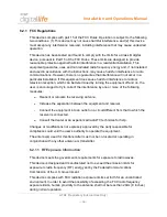
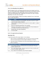
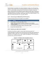
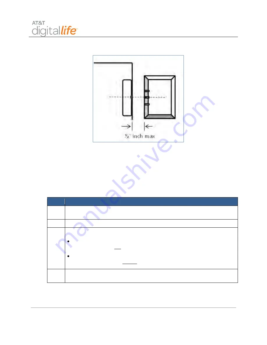
Figure 51:  Mounting Vanishing DW Sensor 


Transmitter—Window 

Select the location where the vanishing sensor is to be located. Mount the transmitter on 

the window jam near the top of the section of the window to be protected. The integral 

magnet should be mounted on the window, within ½ inch of the transmitter with the 

notch on the magnet aligned with the middle notch on the transmitter. 

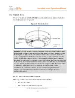
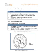
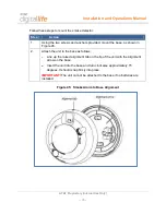
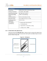
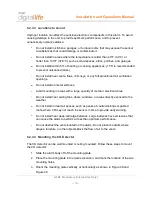
Mounting the Transmitter 

Step 

Action 

1. 

Use the base of the sensor as a template and mark the mounting holes with a 

pencil. 

2. 

Drill the holes for the screws, 5/16” drill size. 

3. 

Mount the base to the door jam with the screws provided  

  For doors that open on the left hand side, the round battery cavity in the 

base should be at top when the base is mounted to the door jam. 

  For doors that open on the right hand side, the round battery cavity in the 

base should be at the bottom when the base is mounted to the door jam. 

4. 

Carefully replace the sensor on the base by aligning the tamper switch with the 

plastic tamper tab and snap the cover down on the base. 

Содержание Digital Life

Страница 1: ...AT T Proprietary Internal Use Only Installation and Operations Manual Version 2 1...

Страница 2: ...AT T Proprietary Internal Use Only...

Страница 3: ...em Operation 9 2 6 Digital Life System Alarm Reporting 12 2 7 Event Notification Service Not Evaluated by UL 12 2 8 Remote Video Monitoring Not Evaluated by UL 13 2 9 Home Automation Control Not Evalu...

Страница 4: ...HPAV Connection 39 5 1 1 Connecting the AC to AC Adapter with Integrated HPAV to the DLC Cabinet 40 5 1 2 Connecting the AC to AC Adapter with Integrated HPAV to the DLC Cabinet 41 5 2 DLC Cabinet In...

Страница 5: ...ng and Registering the Smoke Detector 70 6 2 2 3 Installing the Smoke Detector 70 6 2 2 4 Installing Replacing Batteries 72 6 2 2 5 Testing the Smoke Detector 72 6 2 2 6 Maintaining the Smoke Detector...

Страница 6: ...3 Installing the Transmitter 85 6 2 5 4 Mounting the Magnet Assembly 86 6 2 5 5 Installing Replacing Battery 86 6 2 5 6 Specifications RDW Sensor 87 6 2 6 Glass Break Detector 88 6 2 6 1 Discovering...

Страница 7: ...Mounting Guidelines 103 6 2 9 3 Connecting Wired Zones 104 6 2 9 4 Powering the 915MHz Two Way Keypad 104 6 2 9 5 Connecting Power 105 6 2 9 6 Enrolling the Transmitter 108 6 2 9 7 Final Installation...

Страница 8: ...2 Installing the Battery 121 6 2 12 3 Locating the Transmitter 122 6 2 12 4 Mounting the Transmitter 122 6 2 12 5 Specifications Garage Door Tilt Sensor 122 6 3 IP Camera Not Evaluated by UL 123 6 3...

Страница 9: ...36 7 1 9 Fire Emergency 138 7 1 10 AUX Auxiliary Emergency 139 7 1 11 Police Emergency 140 7 2 Duress Code 141 7 3 Key Fob 141 7 4 Web Access via Digital Life Direct Alarm Manager 142 7 4 1 Check Syst...

Страница 10: ...iscovery Discovery In Progress 20 Figure 17 DLD Devices Screen 21 Figure 18 DLD Specific Device Screen 21 Figure 19 DLD Alarm Manager Information 22 Figure 20 Enabling Signal Strength Monitoring 29 Fi...

Страница 11: ...ss Break Detector 88 Figure 56 Mounting Glass Break Detector Step 1 89 Figure 57 Mounting Glass Break Detector Step 2 90 Figure 58 Installing Replacing Batteries 91 Figure 59 PIR Motion Sensor 93 Figu...

Страница 12: ...w Open 132 Figure 91 Keypad Example Arming Exit Now 133 Figure 92 Keypad BYPASS in Ready to Arm State 133 Figure 93 Keypad Entry Delay Alarm Enter Code to Cancel 134 Figure 94 Ready to Arm 134 Figure...

Страница 13: ...erations Manual AT T Proprietary Internal Use Only xi List of Tables Table 1 UL to DLD Features Mapping 23 Table 2 System Messages on Keypad LCD 147 Table 3 Local Power Failure and Low Battery Warning...

Страница 14: ...ained in the operating instructions unless you are qualified to do so Notice l attention des installateurs de r seaux c bl s Les instructions relatives aux interventions d entretien fournies dans la p...

Страница 15: ...nicht ausdr cklich in der Bedienungsanleitung aufgef hrt sind au er Sie sind zur Durchf hrung solcher Arbeiten qualifiziert Aviso a los instaladores de sistemas CATV Las instrucciones de reparaci n c...

Страница 16: ...olete outlet 10 Protect the power cord from being walked on or pinched particularly at plugs convenience receptacles and the point where they exit from the apparatus 11 Only use attachments accessorie...

Страница 17: ...nated the apparatus may still be connected to the power source The light may go out when the apparatus is turned off regardless of whether it is still plugged into an AC power source Eliminate AC Main...

Страница 18: ...ck and fire hazard Never push objects through the openings in this product Foreign objects can cause electrical shorts that can result in electric shock or fire Service Warnings WARNING Avoid electric...

Страница 19: ...ses Platform wherein the primary communication path between the platforms is provided via AT T Cellular Data Service The DLS includes AT T Digital Life Data Centers and AT T Digital Life Central Monit...

Страница 20: ...Platform and the Premises Platform Optionally a secondary communication path between the Network Platform and the Premises can be established via a Bring Your Own Broadband service which could be bas...

Страница 21: ...troller Board which is the central device in the Premises Platform The DLC Cabinet will be wall mounted in a closet utility room or basement similar to a traditional home security cabinet and adjacent...

Страница 22: ...vide the following at a glance status AC POWER flashes green when powering up and solid green when DLC is operational when DLC starts communicating over AT T Cellular Data Service and or customer prov...

Страница 23: ...rgeable battery NOTE Under local power failure the battery system and wireless broadband LEDs will flash simultaneously The cabinet houses the Digital Life Controller Board which is accessed by openin...

Страница 24: ...g AT T Cellular Data Modem with Integrated Antenna Dual Frequency Wireless Transceiver Module Proprietary one way 433MHz and two way 915MHz 24 Hour Battery Backup Wi Fi Module Z Wave Module 908MHz 2 3...

Страница 25: ...proprietary two way 915MHz radio technology is utilized with wireless keypads and sirens See Figure 5 When they are needed to extend the transmission range of the 433MHz and or 915MHz devices a 433MH...

Страница 26: ...e existing wiring to keypads for powering up to two two way 915MHz wireless keypads See Figure 6 Figure 6 Optional Takeover Module Wired Window Door Contacts and Wireless Keypad Power 2 3 3 Optional Z...

Страница 27: ...y mode While the Digital Life Controller is in the Discovery mode the technician places devices in the Discoverable mode The devices are discovered and registered with the Digital Life Controller See...

Страница 28: ...Fire Emergency Aux Emergency Police Emergency The customer must enter a four 4 digit Security Code into the keypad in order to disarm the system The customer creates their four 4 digit Security Code u...

Страница 29: ...act Device ID Identity of device that has triggered an alarm Alarm Enter Code to Cancel Alarm Canceled Fire Emergency Sent Aux Emergency Sent Police Emergency Sent Within the home a 433MHz one way fou...

Страница 30: ...ion executing on the Digital Life Controller in a customer s home to the AT T Digital Life Monitoring Center via the DMP IP Alarm Receiver Fire with device identification Intrusion with device identif...

Страница 31: ...a Local Power Failure Condition The Digital Life System is equipped with a 24 hour battery backup capability and will continue to operate under local power failure conditions for 24 hours When operati...

Страница 32: ...ition They are equipped with customer replaceable batteries Under normal operating conditions the Proprietary 915MHz Two Way devices including the Keypad Siren and Repeater receive power from AC to DC...

Страница 33: ...access the DLD Web tool using a laptop or wireless tablet device such as an iPad Before the DLT arrives at the customer s home to do the Digital Life Service installation an account will already have...

Страница 34: ...illing Account Number BAN to access the customer s account See Figure 11 Figure 11 DLD Enter Account Number The DLT will then see the customer s account displayed on the Information tab See Figure 12...

Страница 35: ...tary Internal Use Only 17 Devices tab they will see the list of Devices that are registered including the DLC Gateway See Figure 13 Figure 13 DLD Devices Screen NOTE The DLT can delete a device by sel...

Страница 36: ...the DLC Gateway and then the screen depicted in Figure 14 will display Figure 14 DLD DLC Specific Details Screen IMPORTANT The discovery method is basically the same for all of the devices that the D...

Страница 37: ...nternal Use Only 19 In order to discover devices the DLT will select Start Discovery in order to place the DLC in the Discovery mode The DLT will see the screens depicted in Figure 15 and Figure 16 Fi...

Страница 38: ...Installation and Operations Manual AT T Proprietary Internal Use Only 20 Figure 16 DLD Start Discovery Discovery In Progress...

Страница 39: ...e screen The DLT can take the DLC out of the Discovery mode by selecting Stop Discovery If the DLT wants to label or change the label on a specific device the DLT can select the Devices tab which will...

Страница 40: ...roprietary Internal Use Only 22 3 3 Administer DLC Features The administration of DLC features is accomplished by accessing the Alarm Manager Information on the Devices tab in DLD as shown in Figure 1...

Страница 41: ...art enable 4 2 2 5 Auto Stay Arm on Unvacated Premises Enabled Disabled Enabled Auto Stay on Unvacated Premises enable 4 2 4 4 Exit Time and Progress Annunciation Disable for Remote Arm Enabled Disabl...

Страница 42: ...utdown 4 3 2 Swinger Shutdown Disable Enabled Disabled Enabled Enable Swinger Shutdown 4 3 3 Fire Alarm Verification Enabled Disabled Disabled Enable Fire Alarm Verification The Alarm Manager administ...

Страница 43: ...he Abort Delay line 2 Use the drop down menu to select the desired Abort Delay Time 3 Click the Change button 4 Verify that the desired change has been made 3 3 5 Alarm Timeout 1 In order to change th...

Страница 44: ...ange has been made 3 3 9 Abort Sound On Off 1 In order to Abort Sound in the AM Flags section click the Abort sound on off box and a checkmark will appear in the box 2 Click the Change button 3 Verify...

Страница 45: ...ck the Change button 3 Verify that the desired change has been made 3 3 14 Cancel Sound On Off 1 In order to Cancel Sound in the AM Flags section click the Cancel sound on off box and a checkmark will...

Страница 46: ...nter In addition to the photoelectric detector the unit contains an integrated fixed 135 temperature and rate of rise heat sensor that will send an alarm signal based on temperature detected 3 4 Troub...

Страница 47: ...Installation and Operations Manual AT T Proprietary Internal Use Only 29 Figure 20 Enabling Signal Strength Monitoring Figure 21 Signal Strength Monitoring Alert...

Страница 48: ...d by the DLC is being repeated such as by a 433MHz Repeater then the Signal Strength indicator will include a notation that the signal is being repeated as is depicted in Figure 23 Figure 23 Signal St...

Страница 49: ...Switch with a WAN port and four LAN ports AT T Cellular Data Service Module is a cellular data modem that provides connection to AT T Cellular Data Service 433 915MHz Transceiver Module is a dual fre...

Страница 50: ...Installation and Operations Manual AT T Proprietary Internal Use Only 32 Figure 24 AT T Digital Life Controller Cabinet and Internal Components...

Страница 51: ...stallation and Operations Manual AT T Proprietary Internal Use Only 33 Figure 25 DLC Cabinet with Shipping Tray At the time of installation the DLT will install the 24 hour battery backup in the cabin...

Страница 52: ...install a HomePlug AV HPAV to Ethernet Bridge and establish an Ethernet connection with the BHR using a Cat5 cable The DLT will verify that there is a HPAV network connection between the HPAV to Ether...

Страница 53: ...ome using an application executing on their wireless tablet device The DLT will take into consideration AT T Cellular Data Service signal strength measurements when determining where to install the ca...

Страница 54: ...The Functionality for each LED is described below Power LED SOLID Device is receiving electrical power Blinking Device is restarting or setting up security OFF Device is not receiving electrical power...

Страница 55: ...curity pairing between devices Factory Default Pushbutton Used for resetting device to factory default settings STEP 4 Observe LEDs Action Observe the three LEDs on the HPAV to Ethernet Bridge and the...

Страница 56: ...al wiring system between the HPAV to Ethernet Bridge and the DLC AC to AC Adapter with Integrated HPAV The Power LED should be solid green the PLC Link should be flashing green and the Ethernet LED sh...

Страница 57: ...e Only 39 5 1 DLC AC to AC Adapter with Integrated HPAV Connection The DLC cabinet is connected to AC power via an AC to AC Adapter with Integrated HPAV as shown in Figure 26 Figure 26 DLC Cabinet Con...

Страница 58: ...he Power LED should turn solid green NOTE The WAN Port on the DLC should be connected to the Ethernet port on the HPAV Device 3 If the customer has an existing home broadband router go to the router a...

Страница 59: ...o indicate activity 5 1 2 Connecting the AC to AC Adapter with Integrated HPAV to the DLC Cabinet Follow these steps to connect the AC to AC Adapter with integrated HPAV to the DLC Cabinet Action Illu...

Страница 60: ...ife Controller Cabinet includes Four external antennas one cellular data antenna one 915MHz antenna and two 433MHz antennas Five Ethernet ports one wide area network WAN port and four local area netwo...

Страница 61: ...es one way communications using a 433MHz receiver 3 Antenna provides two way communications using a 915MHz transceiver 4 Antenna provides one way communications using a 433MHz receiver 5 Five LEDs pro...

Страница 62: ...a sheetrock wall STEP 1 Install the wall plate on the sheetrock wall Action Using the holes on the wall plate as a template mark the four 4 mounting holes with a pencil and pre drill starter holes us...

Страница 63: ...inet to the wall bracket Action Place the DLC Cabinet flush with the wall plate using the keyhole mounting feature Slide the DLC Cabinet down approximately inch Insert two 2 screws through the DLC Cab...

Страница 64: ...tions Manual AT T Proprietary Internal Use Only 46 STEP 3 Perform the final assembly Action Install the antennas and the battery and close the cabinet door as shown in Figure 30 Figure 30 Final Assemb...

Страница 65: ...holes in the upright position Position the mounting bracket with insertion slots in the downward position Align the four 4 screw holes of the mounting bracket with the four 4 screw holes of the wall p...

Страница 66: ...bracket and wall plate for guidance mark the four 4 mounting holes with a pencil Pre drill starter holes using an appropriate size masonry wood drill bit Use four 4 screws to mount the bracket to the...

Страница 67: ...Cabinet to the wall bracket Action Place the DLC Cabinet flush with the wall plate using the keyhole mounting feature Slide the DLC Cabinet down approximately Insert two 2 screws through the DLC Cabi...

Страница 68: ...Manual AT T Proprietary Internal Use Only 50 STEP 4 Perform the final assembly Action Install the antennas and the battery and close the cabinet door as shown in Figure 34 Figure 34 Final Assembly fo...

Страница 69: ...ure 35 Installing Antennas DLC Cabinet Follow these steps to install the antennas Step Action 1 Locate the 3G antenna and screw into the designated port on the side of the cabinet The 3G antenna is wi...

Страница 70: ...eable battery from leaking fluid due to a breakage in the electrolytic cell thus forming a leak circuit between the battery and the storage box or fixed frame install between these two items a heat an...

Страница 71: ...Device Illustration Insert the blade of a flat screwdriver or dime into the slot on the battery compartment screw and turn one quarter turn to release the door You will see the connector wires STEP 2...

Страница 72: ...ns Manual AT T Proprietary Internal Use Only 54 STEP 3 Install battery Action Device Illustration Insert the battery into the battery compartment STEP 4 Close the door and rotate the battery compartme...

Страница 73: ...ed with a battery If the DLC does not receive three consecutive supervisory messages from a 915MHz device then the device is considered to be offline and an advisory message is automatically sent to t...

Страница 74: ...24 hour battery backup under a local power failure condition The batteries are customer installable The keypad is equipped with a tamper switch which is located on the back side of the unit The keypa...

Страница 75: ...e wires from the AC DC power adapter to the terminals on the back side of the keypad as depicted in Figure 38 and install four AA batteries Plug the AC DC power adapter into AC power outlet When power...

Страница 76: ...o discover the keypad using DLD STEP 1 Power up the Keypad STEP 2 Access the Devices page Action Web Page Once you have access the appropriate account the Information page displays From the Informatio...

Страница 77: ...59 Action Web Page From the Device Details page under the Gateway Specific Details category click the Start Discovery button NOTE This is PHASE 1 of the device registration process The Initializing st...

Страница 78: ...ing the Learn button located on the back of the keypad STEP 5 Review the DLC in Discovery Mode Discovery in Process Action Web Page NOTE This is PHASE 2 of the device discovery and registration proces...

Страница 79: ...ry Action Web Page Verify the device registration 6 1 2 Siren 915MHz The AT T model number SW ATT SRN is a wireless siren that is capable of annunciating alarms and keypad chirps The DLC sends message...

Страница 80: ...it is AC powered and backup battery is good Blinking Green unit is not AC powered and is operating on backup batteries Solid Red unit is AC powered and the backup battery needs to be replaced Off unit...

Страница 81: ...located on the rear of the unit 6 1 3 Device Controller 915MHz Not Evaluated by UL The AT T model number SW ATT WDC Wireless Device Controller is a 915MHz two way device that is used to control AC pow...

Страница 82: ...w these steps to discover and register the device controller Step Action 1 Place the DLC into Discovery Mode in DLD 2 Make the Device Controller discoverable by pressing the Learn button located on th...

Страница 83: ...a the two way 915MHz radio protocol 6 1 4 1 Installing the 915MHz Repeater Install the 915MHz Repeater by plugging the grounded plug into a single socket on a wall AC outlet Then install the retaining...

Страница 84: ...ur the 433MHz devices automatically transmit supervisory messages to the DLC These supervisory messages are also known as heartbeat messages These supervisory messages communicate the identity of the...

Страница 85: ...r supervisory messages to the DLC the messages include an indication of whether the device is operating on power from the AC to DC converter or operating on power from the batteries The Key Fob does n...

Страница 86: ...off and on the user is encouraged to try to correct the interference by one or more of the following measures Reorient or relocate the receiving antenna Increase the separation between the equipment a...

Страница 87: ...itally coded wireless signal to the DLC The wireless signal will be repeated every 20 seconds as long as smoke is still present In order to reduce the likelihood of reporting false smoke alarms the Fi...

Страница 88: ...emove the back mounting bracket sends tamper signal 3 Confirm that the smoke detector has been discovered in DLD 4 Label the smoke detector in DLD 6 2 2 3 Installing the Smoke Detector Follow these st...

Страница 89: ...ase as shown in Figure 45 2 Attach the unit to the base as follows Line up the raised alignment tab on the lip of the unit with the alignment arrow on the base Insert the unit into the base and turn c...

Страница 90: ...over away from the smoke alarm to unsnap it and lift it off 3 Remove the batteries and dispose of them properly 4 Observing correct polarity insert two new CR123A 3V lithium batteries into the battery...

Страница 91: ...d and used properly they require minimal maintenance Follow these guidelines Test the unit weekly Clean the cover with a dry or damp water cloth as needed to keep it free from dust and dirt When a uni...

Страница 92: ...5 6 x 2 4 14 2 cm x 6 1cm Base dimensions 5 4 x 0 46 13 7 cm x 1 17cm Drift compensation adjustment 0 5 ft max Heat detector specifications Rate of rise 15 F min 105 F 8 3 C min 40 6 C Fixed 135 F 5 F...

Страница 93: ...Discovering and Registering the CO Detector Follow these steps to discover and register the CO detector Step Action 1 Place the DLC into Discovery Mode in DLD 2 Make the CO detector discoverable by i...

Страница 94: ...surfaces Avoid mounting in areas with a large quantity of metal or electrical wires Do not install near ceiling fans doors windows or areas directly exposed to the weather Do not install in dead air...

Страница 95: ...all drill a 3 16 in hole and use the plastic anchors provided 2 After the mounting plate is secured slide the alarm over the mounting plate 3 Complete labels and attach Two labels have been provided t...

Страница 96: ...es NOTE Place the DLC into sensor test mode prior to replacing the batteries If the DLC is not in sensor test mode during battery replacement an alarm tamper condition may be reported 1 Slide the alar...

Страница 97: ...ontinuous exposure to the high sound level of this alarm over an extended period of time may cause hearing loss The CO Detector has one 1 test mode Normal CO Alarm Test This test mode allows you to co...

Страница 98: ...r quick beeps 5 seconds silence repeating Alarm condition Dangerous concentrations of CO detected See Alarm procedure on page 8 Low battery low battery hush Red Alarm LED flashes every 60 seconds One...

Страница 99: ...ansmitter that sends information to the DLC Opening the door or window will cause the radio transmitter to send an alarm report Closing the door or window will cause the radio transmitter to send a re...

Страница 100: ...er Mounting the Transmitter Step Action 1 Use the base of the sensor as a template and mark the mounting holes with a pencil 2 Drill the holes for the screws 5 16 drill size 3 Mount the base to the do...

Страница 101: ...ransmitter with double stick tape is not allowed in UL installations For non UL listed systems the sensor can be permanently mounted using the supplied adhesive 6 2 4 3 Installing Replacing Battery Th...

Страница 102: ...Discovering and Registering the RDW Sensor Follow these steps to discover and register the RDW sensor Step Action 1 Place the DLC into Discovery Mode in DLD 2 Make the RDW sensor discoverable by inser...

Страница 103: ...performance of the transmitter portion of the device 6 2 5 3 Installing the Transmitter The hardware kit for the RDW sensor provides additional plastic parts for securing the transmitter to the door...

Страница 104: ...door jam 11 If you are mounting the transmitter into the side of the door jam proceed as follows Slide the transmitter assembly into the 7 8 inch hole 6 2 5 4 Mounting the Magnet Assembly The integra...

Страница 105: ...ssembly into the door or window jam 9 Install the screws for securing the transmitter if they were used in the initial installation process 10 Test the RDW sensor to ensure that it is working properly...

Страница 106: ...ction as shown in Figure 55 Figure 55 Glass Break Detector 6 2 6 1 Discovering and Registering the Glass Break Detector Follow these steps to discover and register the glass break detector Step Action...

Страница 107: ...tall the two CR123A batteries supplied with the unit paying careful attention to observe the correct battery polarity 3 Wait five 5 seconds for the power up delay Follow these steps to mount the Glass...

Страница 108: ...st button should be oriented down nearest the floor 4 When attaching the detector to the base match the alignment marks and twist clockwise as shown in Figure 57 Figure 57 Mounting Glass Break Detecto...

Страница 109: ...Installing Replacing Batteries Follow these steps to install or replace the batteries Step Action 1 Remove the detector from the base by turning it counterclockwise 2 Remove the depleted batteries and...

Страница 110: ...ass breaking sound NOTE Use a glass break simulator such as the Intellisense Model FG 701 Wireless Range RF Test Step Action 1 Push and hold the test button for five 5 seconds and release The red LED...

Страница 111: ...Break Simulator Intellisense Model FG 701 6 2 7 Motion Detector PIR The AT T model number SW ATT PIR is a fully supervised tamper protected infrared motion detector with pet immunity that reports to...

Страница 112: ...3 Confirm that the PIR motion sensor has been discovered in DLD 4 Label the PIR motion sensor in DLD 6 2 7 2 Selecting a Mounting Location Select a location for the PIR so that an intruder will cross...

Страница 113: ...on that is at least 7 feet and less than 8 feet above the floor to mount the PIR 3 Mount the selected part to the wall using the supplied screws and anchors 4 Place the back plate assembly onto the sh...

Страница 114: ...g the device on the bottom 6 2 7 5 Corner Mounting 1 Press the button on the bottom of the PIR to disengage the back plate 2 Using a small Philips head screwdriver remove the plastic from the top moun...

Страница 115: ...immunity is required 2 The 25K and High Sensitivity setting allow for pet immunity for animals of up to 55 pounds while providing excellent coverage 3 The use of the Low Sensitivity setting is not re...

Страница 116: ...sensor includes a walk test feature Test the PIR by following these steps Step Action 1 To enter the Walk RF Test mode press the button on the right hand side of the PIR The PIR will remain in the Wa...

Страница 117: ...n of the Digital Life System including door window sensors and motion detectors Disarm Button Disarms the security portion of the Digital Life System Arm Stay Button Arms the window door sensors only...

Страница 118: ...bottom of the key fob and turn it 90 degrees 2 Use a small Philips head screwdriver to remove the screw located in the center of the printed circuit board Do not discard the screws 3 Remove the print...

Страница 119: ...9 Takeover Module When Digital Life installations are performed in locations with existing wired security systems an AT T model number SW ATT TAKE Takeover Module may be utilized to re use the existi...

Страница 120: ...me installations it may be installed in a different location in the home All of the zones in the Takeover Module act as supervised wireless zones in the DLS NOTE DO NOT connect the DLC Cabinet to an A...

Страница 121: ...s Alternate Method Press the tamper switch located in the middle of the board 3 Confirm that the takeover module has been discovered in DLD 4 Label the takeover module and zones in DLD 6 2 9 2 Install...

Страница 122: ...ove leads from battery on existing wired panel 3 With power removed disconnect the hardwired zones from the existing panel 4 Remove the supplied resistor from the zone s connector to be used 5 Each ha...

Страница 123: ...tors in the Takeover Module as shown in Figure 68 Figure 68 Takeover Module Powering 915MHz Two Way Keypad The Takeover Module can be used to power one or two 915MHz Two Way Keypads If the Takeover Mo...

Страница 124: ...Module illuminates solid when the batteries are fully or partially charged flashes when the batteries are low and is off when not powered Follow these instructions to connect the Takeover Module to a...

Страница 125: ...r wires to the AC to DC power adapter NOTE Pay close attention to the polarity and indicated on the AC to DC power adapter 4 Plug the AC to DC power adapter into an AC power outlet See Figure 71 5 Ins...

Страница 126: ...the AC to DC Adapter to an AC power outlet that is controlled by a switch 6 2 9 6 Enrolling the Transmitter Install the batteries in the Takeover Module while the DLC is in the Discovery mode Once th...

Страница 127: ...Slide bracket over all the wire pairs The wire pairs go into the long slot 2 Turn the bracket half a turn to capture the wires 3 Slide the bracket into the slots on the case back STEP 2 Install the ca...

Страница 128: ...ak devices 6 2 9 8 Specifications Takeover Module General Specifications Wireless signal range TBD 350ft open air Code Outputs For device Power up Tamper Low battery Supervisory AC power DC battery po...

Страница 129: ...for the RPT4 changes from AC power to battery backup or from battery backup to AC power the RPT4 will automatically send a message to the DLC within two 2 minutes indicating that the power source has...

Страница 130: ...ntermittently when non learned RF packets are received 6 2 10 2 Repeater Function When the RTP4 repeater receives a transmission for a 433MHz device the following occurs For unlearned transmitters the...

Страница 131: ...button 2 Continue to hold the Learn button 3 After approximately five 5 seconds the LED counts out the number of transmitters learned by the repeater by blinking one 1 time for every transmitter lear...

Страница 132: ...stall the 433MHz repeater plug it into a 120V AC outlet Use the retaining screw to secure the repeater into the AC wall socket Back up power for the SW ATT RPT4 is provided by two 2 lithium CR123A non...

Страница 133: ...ndition Low Battery Low Battery Restore AC Power Source DC Power Source 6 2 10 9 Installing Replacing Batteries The repeater has two non rechargeable CR123 batteries as a backup power supply The batte...

Страница 134: ...eck the installation section for required wiring for the sensor if it is used in temperature only configuration The temperature sensor does not send a restore message but does send an ambient temperat...

Страница 135: ...nd mark the locations with a pencil 2 Drill the holes for the screws 3 Secure the mounting plate with the screws provided 4 Secure the sensor to the mounting plate by carefully guiding the sensor over...

Страница 136: ...eration The flood detector is supplied with a four foot wire that is connected to the flood sensor See Figure 75 1 Connect the flood sensor to the screw terminals located on the sensor circuit board 2...

Страница 137: ...ttery is low replace it immediately The temperature flood sensor requires one 3 Volt CR2 lithium battery See Figure 76 for steps concerning installing the battery Figure 76 Install Battery in Temperat...

Страница 138: ...a minimum angle of 45 degrees the sensor will initiate an alarm or garage door open condition The sensor will also send a restore or garage door closed condition when the tamper switch is returned to...

Страница 139: ...the screwdriver 90 degrees 2 Place a small flathead screwdriver in the slot between the metal clip and the battery then twist the screwdriver slightly while holding back one of the black plastic edges...

Страница 140: ...the transmitter do the following 1 To remove the sensor cover from the base press a flathead screwdriver into the slot on the bottom of the sensor Figure 77 and turn the screwdriver 90 2 Use the base...

Страница 141: ...C Adapter with Integrated HPAV To connect an IP Camera AC DC adapter with integrated HPAV do the following Step Device Photo Illustration 1 Go to each location where you want to install an IP camera a...

Страница 142: ...thernet cable into an available port on the customer s Broadband Home Router BHR 3 Connect the DC power cord from the camera AC to DC adapter into the power port on the back of the camera 4 Plug the c...

Страница 143: ...Z Wave device controller as shown in Figure 78 Figure 78 Indoor Power Outlet Controller Module This Z Wave appliance switch can be utilized to control turning lamps and other small appliances on and...

Страница 144: ...Mode in DLD 2 Plug in the Indoor Power Outlet Controller Module and once it has powered make it discoverable by pressing the learn button on the side of the module 3 Confirm that the Indoor Power Out...

Страница 145: ...on concerning the status of the system The system has three 3 primary states Ready to Arm all of the supervised devices are in the closed state Not Ready to Arm one or more of the supervised devices i...

Страница 146: ...st enter a four 4 digit Security Code into the keypad in order to disarm the system The customer creates their four 4 digit Security Code using a Web tool The customer uses the same Web tool to create...

Страница 147: ...umber of devices that are not in the closed state as shown in Figure 81 Figure 81 Keypad Number of Open State Devices Afterwards the keypad will display the name of the open state device s and cycle t...

Страница 148: ...LCD displays Arming Exit Now as shown in Figure 84 Figure 84 Keypad Arming Exit Now You should exit through the designated entry exit door s before the exit delay time period expires After the exit de...

Страница 149: ...ypad chirps and the LCD displays Arming Exit Now as shown in Figure 86 Figure 86 Keypad Arming Exit Now You should exit through the designated entry exit door s before the exit delay time period expir...

Страница 150: ...s is in an opened state such as a window and or door as shown in Figure 88 You may close the open sensor s before arming or utilize the BYPASS feature Figure 88 Keypad Number of Open State Devices Th...

Страница 151: ...fore the exit delay time period expires After the exit delay time period expires the system is in the Armed STAY or Armed AWAY mode The ARMED Red LED is illuminated and the LCD displays Armed STAY or...

Страница 152: ...the keypad begins chirping The entry delay allows you to get to the keypad and enter your code before the system sounds an alarm The keypad chirps slowly for during the entry delay and then chirps fas...

Страница 153: ...sarming the System When the system is in the Armed STAY mode you enter the four 4 digit Security Code to disarm the system See Figure 95 Figure 95 Keypad Armed STAY After you enter the four 4 digit Se...

Страница 154: ...ted window or door while the system is armed the siren will start sounding the keypad starts chirping and the LCD displays Alarm Enter Code to Cancel as shown in Figure 97 Figure 97 Keypad Alarm Enter...

Страница 155: ...y Internal Use Only 137 You can clear the alarm by entering your four 4 digit Security Code The LCD will display Alarm Canceled and then Ready to Arm as shown in Figure 99 and Figure 100 Figure 99 Key...

Страница 156: ...Digital Life Central Monitoring Center and the keypad will display Fire Emergency Sent as shown in Figure 101 and Figure 102 Figure 101 Keypad Confirm Fire Figure 102 Keypad Fire Alarm Sent The alarm...

Страница 157: ...ency Alarm will automatically be sent to the AT T Digital Life Central Monitoring Center and the LCD will display AUX Emergency Sent as shown in Figure 104 and Figure 105 Figure 104 Keypad Confirm AUX...

Страница 158: ...to the AT T Digital Life Central Monitoring Center and the LCD will display Police Emergency Sent as shown in Figure 107 and Figure 108 Figure 107 Keypad Confirm Police Emergency Figure 108 Keypad Pol...

Страница 159: ...he Duress Code generates a silent alarm The siren will not sound and there will be no indication on the display that the Duress Code has been entered 7 3 Key Fob A 433MHz one way four button key fob p...

Страница 160: ...rect web interface The Alarm Manager application can be utilized to Check System Status Arm the system in the Armed STAY mode Arm the system in the Armed AWAY mode Disarm the system 7 4 1 Check System...

Страница 161: ...within DLD by clicking the Devices tab and viewing Alarm Manager Information 2 Click the Arm Away or Arm Stay button 3 Wait a few seconds 4 Refresh the browser 5 Verify that the System Status is Arme...

Страница 162: ...Manual AT T Proprietary Internal Use Only 144 STEP 3 Wait a few seconds STEP 4 Refresh the browser STEP 5 Verify that the System Status is Armed AWAY or Armed STAY Digital Life Direct Armed AWAY Digi...

Страница 163: ...system 1 Access the System Status page within DLD by clicking the Devices tab and viewing Alarm Manager Information 2 Click the Disarm button 3 Wait a few seconds 4 Refresh the browser 5 Verify that...

Страница 164: ...Installation and Operations Manual AT T Proprietary Internal Use Only 146 STEP 4 Refresh the browser STEP 5 Verify that the System Status is HOME Disarmed...

Страница 165: ...ing Center System Battery Failure DLC Cabinet 24 hour backup battery is failing or has failed and needs to be replaced Maintenance Mode Software is being upgraded on the DLC Cabinet Fire Alarm Sent A...

Страница 166: ...IRE button on keypad Fire Emergency Sent Confirmation that Fire Emergency has been sent to Digital Life Central Monitoring Center Press to confirm AUX Confirm pressing AUX button on keypad Aux Emergen...

Страница 167: ...AWAY mode Alarm Enter Code to Cancel Enter Security Code to cancel alarm Alarm Cancelled Confirms that a valid Security Code has been entered and an alarm has been cancelled Press STAY or AWAY BYPASS...

Страница 168: ...uipped with 24 hour battery backup and will continue to operate for 24 hours under a local power failure condition They are equipped with customer replaceable batteries When the Digital Life System DL...

Страница 169: ...ress to Silence Four 4 hours from pressing to Silence DLC Cabinet AC Power Failure DLC Cabinet System Operating Battery Backup then Press to Silence Four 4 hours from pressing to Silence UL 985 Smoke...

Отзывы: