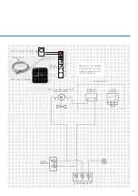
A weather compensator can be fitted to any combi boiler in the range. It can also be fitted on a system boiler with a 3-port
diverter valve and ONE controller kit. The ONE is an OpenTherm thermostat and will overrule some settings in the boiler.
The external weather compensation probe controls the maximum primary flow temperature output to the heating circuit
according to the outside temperature.
Operation:
During a central heating on period the weather compensation sensor monitors the external temperature and modulates
the boiler heating output to give the correct flow temperature to maintain the required room temperature.
If the external temperature drops, then the flow temperature will increase and if the external temperature increases,
then the flow temperature will decrease. This improves efficiency which reduces the amount of wasted energy and
reduces gas consumption.
The radiator temperature will vary and on mild day the radiators will not feel as hot as on a cold day, this is normal and
not a fault with the boiler or heating circuit. The room temperature will still be maintained as set by the room thermostat.
Flue lengths
Concentric Flue system Ø 60 / 100mm & 80 / 125mm
Dimensions flue gas system and air supply system.
Maximum equivalent flue length = distance between boiler
(from elbow or vertical adapter) and the end of terminal.
BOILER
MAXIMUM HORIZONTAL OR VERTICAL
EQUIVALENT FLUE LENGTH
(
Ø 60/100mm)
(
Ø 80/125mm)
iC24, iC28, iC Economiser 27
iR12, iR15, iR18, iR24
iS12, iS15, iS18, iS24
18m
50m
iC36, iC40
iC Economiser 35, iC Economiser 39
iR32, iR40
iS32, iS40
6m
45m
FLUE BEND
EQUIVALENT FLUE LENGTH
(
Ø 60/100mm)
(
Ø 80/125mm)
87° bend resistance length
1.6m
3.0m
45° bend resistance length
1.0m
1.9m
Weather compensator
Installing the probe
The external probe must be installed on a North
or North West facing wall (if possible) at a height
of at least 3 meters from the ground. It must be
in a position where it is not exposed to direct
sunlight, warm air currents and cannot be
tampered with. The probe can be installed
horizontally or vertically to a wall or under the
eaves of a roof.
21
Содержание BC100124
Страница 1: ...Appliance Technical Guide SERVICE ENGINEER EDITION ...
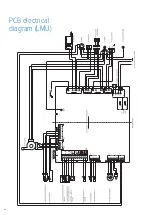
Страница 24: ...PCB electrical diagram LMU 24 ...
Страница 35: ...Notes 35 ...


