


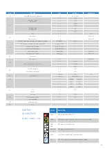


Error codes
ERROR
CODE
ERROR DESCRIPTION
CHECKS
10
Outside sensor error (e.g. open, short circuit, out of range)
Check the sensor
Check the wiring harness for continuity
Check wiring harness not shorting to earth
Check no water leaks affecting wiring harness
Check connection on PCB are connected properly
20
Flow sensor error (e.g. open, short circuit, out of range)
Check the sensor not short or open circuit
Check wiring harness connections between sensor & PCB
40
Return sensor error (e.g. open, short circuit, out of range)
Check the sensor not short or open circuit
Check wiring harness connections between sensor & PCB
50
T3 (DHW) sensor error (e.g. open, short circuit, out of range)
Check the sensor not short or open circuit
Check wiring harness connections between sensor & PCB
61
Bus communication error (contact open)
Check connection on blue connector on PCB
Check connection on ONE controller back plate
Check cable between ONE controller and PCB
78
Water pressure outside of range or not connected (combi & system boiler)
Check water pressure on analogue gauge
Check the sensor
Check wiring harness not shorting to earth
Check the connection plug on top of sensor and PCB
If boiler does not see a pressure rise after 6 attempts (x 10min)
C118 with spanner will go to C78 with bell
105
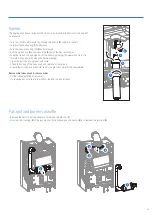
Venting program active when power turned on or interrupted (runs approx. 7 mins.)
Wait for venting programme to finish (runs approx. 7 mins.)
110
Safety temperature exceeded
Temperature rise too fast. Check correct circulation of the
water and pump
111
Maximum temperature exceeded
Check the flow sensor not short or open circuit
Check correct circulation of the water and pump
117
Pressure too high (> 3 bar) or pump pressure increase too high (combi & system boiler)
Check water pressure on analogue gauge
118
Pressure too low (< 1 bar) or pump pressure increase too low (no pump detection) (combi & system
boiler)
Check water pressure on analogue gauge
Check 230V to pump
Check pump is spinning via de-blocking centre screw
Check PWM pump connection pins, cable and PCB connection X1
119
Link on X2 position 4 and 5 missing (combi & system boiler)
Check link and link connection to wiring harness
Check wiring harness
Check connection onto PCB X2 4 & 5
129
Fan error (fan does not start up)
Check fan and cable
133
No flame after 5 ignition attempts
Check gas supply and flue system correct (in. condensate)
Check connection between gas valve and PCB
Check connection between spark generator and PCB
Check connections between spark generator and electrode
Check sensing lead connection between electrode and PCB
151
Fan error (speed control is not achieved or is out of range) or control unit defective
Check fan and cable
Check PCB
154
Flow increases too fast ∆T too large, return > flow
Check correct circulation of the water and pump
Check gradient setting
164
Flow switch not closed at heat demand (system pump not running) (regular boiler)
Check flow and return are the right way round
Check correct circulation of the water and pump
180
No error: shortly visible when leaving chimney sweep function
181
No error: shortly visible when leaving commissioning mode
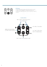
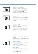
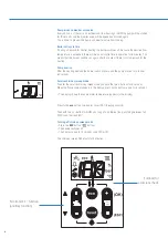
A detected failure is indicated on the
display in blocking or error messages.
Blocking code with spanner symbol
Error is temporary and will cancel itself or will
lock the boiler after several attempts (error).
Error code with bell symbol
Error means a lock on the boiler and can only
be remedied by a reset and/or intervention by
a service technician.
22
Содержание BC100124
Страница 1: ...Appliance Technical Guide SERVICE ENGINEER EDITION ...
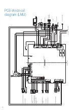
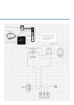
Страница 24: ...PCB electrical diagram LMU 24 ...
Страница 35: ...Notes 35 ...