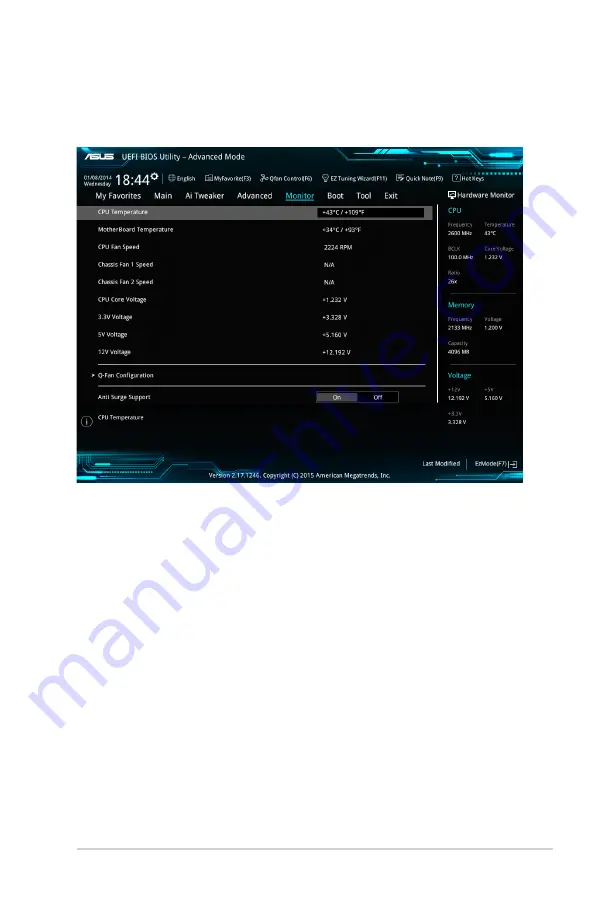
background image

2.7 

Monitor menu

The Monitor menu displays the system temperature/power status, and allows you to change 

the fan settings.
Scroll down to display the other BIOS items.

2.7.1 

CPU/ MB Temperature [xxx

º

C/xxx

º

F]/ [Ignore]

The onboard hardware monitor automatically detects and displays the CPU and motherboard 

temperatures. 

Select 

[Ignore]

 if you do not wish to display the detected temperatures.

2.7.2 

CPU Fan/ Chassis Fan 1/2 Speed [xxxx RPM]/ [Ignore]/ 

[N/A]

The onboard hardware monitor automatically detects and displays the CPU and chassis fan 

1/2 speeds in rotations per minute (RPM). If the fan is not connected to the motherboard, the 

field shows N/A. Select 

[Ignore]

 if you do not wish to display the detected speed.

2.7.3 

CPU Input Voltage (VCCIN), CPU Core Voltage, 3.3V 

Voltage, 5V Voltage, 12V Voltage

The onboard hardware monitor automatically detects the voltage output through the onboard 

voltage regulators. Select 

[Ignore]

 if you do not want to detect this item.

ASUS Z170M-PLUS

2‑39

Содержание Z170M-PLUS

Страница 1: ...Motherboard Z170M PLUS ...

Страница 2: ...spective companies and are used only for identification or explanation and to the owners benefit without intent to infringe Offer to Provide Source Code of Certain Software This product contains copyrighted software that is licensed under the General Public License GPL under the Lesser General Public License Version LGPL and or other Free Open Source Software Licenses Such software in this product...

Страница 3: ...System memory 1 7 1 5 Expansion slots 1 10 1 6 Headers 1 12 1 7 Connectors 1 13 1 8 Onboard LED 1 23 1 9 Software support 1 24 Chapter 2 BIOS information 2 1 Managing and updating your BIOS 2 1 2 2 BIOS setup program 2 6 2 3 My Favorites 2 16 2 4 Main menu 2 18 2 5 Ai Tweaker menu 2 20 2 6 Advanced menu 2 30 2 7 Monitor menu 2 39 2 8 Boot menu 2 43 2 9 Tool menu 2 48 2 10 Exit menu 2 49 Appendices...

Страница 4: ...erboard and adding components carefully read all the manuals that came with the package Before using the product ensure all cables are correctly connected and the power cables are not damaged If you detect any damage contact your dealer immediately To avoid short circuits keep paper clips screws and staples away from connectors slots sockets and circuitry Avoid dust humidity and temperature extrem...

Страница 5: ...ks properly take note of the following symbols used throughout this manual DANGER WARNING Information to prevent injury to yourself when completing a task CAUTION Information to prevent damage to the components when completing a task IMPORTANT Instructions that you MUST follow to complete a task NOTE Tips and additional information to help you complete a task Typography Bold text Indicates a menu ...

Страница 6: ...P Hyper DIMM support is subject to the physical characteristics of individual CPUs Please refer to Memory QVL Qualified Vendors List for details Graphics Integrated graphics processor Intel HD Graphics support Multi VGA output support HDMI DVI D RGB ports Supports HDMI with maximum resolution of 4096 x 2160 24Hz 2560 x 1600 60Hz Supports DVI D with maximum resolution of 1920 x 1200 60Hz Supports R...

Страница 7: ... on the M 2 socket SATA Express supports devices in both PCIe and SATA modes When a device in SATA mode is installed on the M 2 socket SATA Express supports one PCIe mode device or one SATA mode device installed on SATA6G_2 connector only In this setup the system sets a higher priority for M 2 socket than the SATA Express connector These functions work depending on the type of CPU installed LAN In...

Страница 8: ...rger ASUSAI Suite 3 ASUS Disk Unlocker featuring 3TB HDD support ASUS Anti Surge EZ DIY Push Notice Monitor your PC status with smart devices in real time UEFI BIOS EZ Mode Featuring friendly graphics user interface ASUS O C Tuner ASUS CrashFree BIOS 3 ASUS EZ Flash 3 Q Design ASUS Q Slot ASUS Q DIMM ASUS Exclusive Overclocking Features Precision Tweaker 2 vCore Adjustable CPU core voltage at 0 00...

Страница 9: ...utput Internal I O Connectors 2 x USB 3 0 2 0 connector support additional 4 USB 3 0 2 0 ports 19 pin 2 x USB 2 0 1 1 connectors support additional 4 USB 2 0 1 1 ports 1 x M 2 Socket 3 for M Key type 2242 2260 2280 devices 1 x SATA Express connector compatible with 2 x SATA 6 0 Gb s ports 6 x SATA 6 0 Gb s connectors gray 2 from SATA Express 1 x 4 pin CPU fan connector for both 3 pin DC mode and 4...

Страница 10: ...k Note Last Modified Log F12 PrintScreen function and ASUS DRAM SPD Serial Presence Detect memory information Manageability WfM 2 0 DMI 3 0 WOL by PME PXE Support DVD Drivers ASUS utilities EZ Update Anti virus software OEM version OS support Windows 10 64 bit Windows 8 1 64 bit Windows 7 32 bit 64 bit Please refer to ASUS official website and download Windows 7 Installation Guide and EZ Installer...

Страница 11: ...he power supply Failure to do so may cause severe damage to the motherboard peripherals or components 1 2 Motherboard overview Before you install the motherboard study the configuration of your chassis to ensure that the motherboard fits Unplug the power cord before installing or removing the motherboard Failure to do so can cause you physical injury and damage to motherboard components 1 2 1 Plac...

Страница 12: ... VGA CLRTC 22 7cm 8 95in DDR4 DIMM_A1 64bit 288 pin module DDR4 DIMM_A2 64bit 288 pin module DDR4 DIMM_B1 64bit 288 pin module DDR4 DIMM_B2 64bit 288 pin module USB_C1 HDMI USB3_78 CHA_FAN2 CHA_FAN1 CPU_FAN LGA1151 DIGI VRM COM SPDIF_OUT EATX12V USB3_34 USB3_12 Intel Z170 Intel I219V PANEL SB_PWR AUDIO SATA6G_4 SATA6G_3 SATA6G_5 SATA6G_6 Super I O SATAEXPRESS SATA6G_1 SATA6G_2 24 4cm 9 6in LAN_USB...

Страница 13: ...6 Standby power LED SB_PWR 1 23 7 USB 3 0 connectors 20 1 pin USB3_12 USB3_34 1 16 8 Intel Z170 Serial ATA 6 0Gb s connectors 7 pin SATA 6G_1 6 SATA EXPRESS 1 21 9 System panel connector 20 5 pin PANEL 1 22 10 Clear RTC RAM 2 pin CLRTC 1 12 11 USB 2 0 connectors 10 1 pin USB1112 USB1314 1 15 12 Serial port connectors 10 1 pin COM 1 15 13 LPT connector 26 1 pin LPT 1 18 14 Front panel audio connect...

Страница 14: ... and LGA1156 sockets on the LGA1151 socket Upon purchase of the motherboard ensure that the PnP cap is on the socket and the socket contacts are not bent Contact your retailer immediately if the PnP cap is missing or if you see any damage to the PnP cap socket contacts motherboard components Keep the cap after installing the motherboard ASUS will process Return Merchandise Authorization RMA reques...

Страница 15: ...ASUS Z170M PLUS 1 5 1 3 1 Installing the CPU 1 2 3 A B A B C 5 4 ...

Страница 16: ...tion 1 3 2 CPU heatsink and fan assembly installation Apply the Thermal Interface Material to the CPU heatsink and CPU before you install the heatsink and fan if necessary 3 4 To install the CPU heatsink and fan assembly 2 B A A B 1 ...

Страница 17: ...ory Module DIMM sockets A DDR4 module is notched differently from a DDR DDR2 or DDR3 module DO NOT install a DDR DDR2 or DDR3 memory module to the DDR4 slot The figure illustrates the location of the DDR4 DIMM sockets According to Intel CPU spec DIMM voltage below 1 35 V is recommended to protect the CPU Z170M PLUS Z170M PLUS 288 pin DDR4 DIMM sockets DIMM_A1 DIMM_A2 DIMM_B1 DIMM_B2 ...

Страница 18: ... you are using a 32 bit Windows OS Install a 64 bit Windows OS if you want to install 4GB or more on the motherboard For more details refer to the Microsoft support site at http support microsoft com kb 929605 en us The default memory operation frequency is dependent on its Serial Presence Detect SPD which is the standard way of accessing information from a memory module Under the default state so...

Страница 19: ...ASUS Z170M PLUS 1 9 1 4 3 Installing a DIMM 1 2 3 To remove a DIMM B A ...

Страница 20: ...y seated on the slot 5 Secure the card to the chassis with the screw you removed earlier 6 Replace the system cover 1 5 2 Configuring an expansion card After installing the expansion card configure it by adjusting the software settings 1 Turn on the system and change the necessary BIOS settings if any See Chapter 2 for information on BIOS setup 2 Assign an IRQ to the card 3 Install the software dr...

Страница 21: ...HA_FAN1 2 when using multiple graphics cards for better thermal environment VGA configuration PCI Express operating mode PCIe 3 0 x16_1 gray PCIe 3 0 x16_2 Single VGA PCIe card x16 Recommended for single VGA card N A Dual VGA PCIe cards x16 x4 IRQ assignments for this motherboard A B C D PCIEx16_1 shared PCIEx16_2 shared PCIEx1_1 shared PCIEx1_2 shared Intel GBE LAN shared USB 3 0 Controller share...

Страница 22: ...ct such as a screwdriver to short the two pins 3 Plug the power cord and turn on the computer 4 Hold down the Del key during the boot process and enter BIOS setup to re enter data If the steps above do not help remove the onboard battery and short the two pins again to clear the CMOS RTC RAM data After clearing the CMOS reinstall the battery You do not need to clear the RTC when the system hangs d...

Страница 23: ...the function of the audio ports in 2 1 4 1 5 1 or 7 1 channel configuration 1 PS 2 mouse port green This port is for a PS 2 mouse 2 Video Graphics Adapter VGA port This 15 pin port is for a VGA monitor or other VGA compatible devices 3 LAN RJ 45 port This port allows Gigabit connection to a Local Area Network LAN through a network hub LAN port LED indications LAN port Speed LED Activity Link LED A...

Страница 24: ...rts These 9 pin Universal Serial Bus USB ports are for USB 3 0 devices Due to the limitation of USB 3 0 controller USB 3 0 devices can only be used under Windows OS environment and after the USB 3 0 driver installation We strongly recommend that you connect USB 3 0 devices to USB 3 0 ports for faster and better performance from your USB 3 0 devices 9 USB 5Gb s Type C port This 24 pin Universal Ser...

Страница 25: ...e to any of these connectors then install the module to a slot opening at the back of the system chassis These USB connectors comply with USB 2 0 specifications and supports up to 480Mbps connection speed Z170M PLUS Z170M PLUS Serial port COM connector PIN 1 COM DCD TXD GND RTS RI RXD DTR DSR CTS Never connect a 1394 cable to the USB connectors Doing so will damage the motherboard The USB 2 0 modu...

Страница 26: ...ces optimized power efficiency and backward compatibility with USB 2 0 The USB 3 0 module is purchased separately Z170M PLUS Z170M PLUS USB3 0 Front panel connectors USB3_12 USB3 5V IntA_P1_SSRX IntA_P1_SSRX GND IntA_P1_SSTX IntA_P1_SSTX GND IntA_P1_D IntA_P1_D GND PIN 1 USB3 5V IntA_P2_SSRX IntA_P2_SSRX GND IntA_P2_SSTX IntA_P2_SSTX GND IntA_P2_D IntA_P2_D USB3_34 A B A B GND IntA_P1_D IntA_P1_D ...

Страница 27: ...se a power supply unit PSU that complies with ATX 12 V Specification 2 0 or later version and provides a minimum power of 350 W DO NOT forget to connect the 4 pin 8 pin ATX 12V power plug Otherwise the system will not boot up We recommend that you use a PSU with higher power output when configuring a system with more power consuming devices or when you intend to install additional devices The syst...

Страница 28: ...connector set the item to AC97 By default this connector is set to HD 6 LPT connector 26 1 pin LPT The LPT Line Printing Terminal connector supports devices such as a printer LPT standardizes as IEEE 1284 which is the parallel port interface on IBM PC compatible computers Z170M PLUS Z170M PLUS Front panel audio connector AAFP AGND NC SENSE1_RETUR SENSE2_RETUR PORT1 L PORT1 R PORT2 R SENSE_SEND POR...

Страница 29: ...Ie and SATA modes When a device in PCIe mode is installed on the M 2 socket SATA Express supports devices in both PCIe and SATA modes When a device in SATA mode is installed on the M 2 socket SATA Express supports one PCIe mode device or one SATA mode device installed on SATA6G_2 connector only In this setup the system sets a higher priority for M 2 socket than the SATA Express connector The M 2 N...

Страница 30: ...nside the system may damage the motherboard components These are not jumpers Do not place jumper caps on the fan connectors The CPU_FAN connector supports a CPU fan of maximum 1A 12 W fan power Only the 4 pin CPU fan supports the ASUS FAN Xpert 3 feature 9 CPU and chassis fan connectors 4 pin CPU_FAN 4 pin CHA_FAN 1 2 Connect the fan cables to the fan connectors on the motherboard ensuring that th...

Страница 31: ...et SATA Express supports one PCIe mode device or one SATA mode device installed on SATA6G_2 connector only In this setup the system sets a higher priority for M 2 socket than the SATA Express connector The SATA EXPRESS connector can support one SATA Express device or at most two SATA devices SATA6G_6 GND RSATA_TXP3 RSATA_TXN3 GND RSATA_RXN3 RSATA_RXP3 GND GND RSATA_TXP6 RSATA_TXN6 GND RSATA_RXN6 R...

Страница 32: ... 2 pin HDD_LED This 2 pin connector is for the HDD Activity LED Connect the HDD Activity LED cable to this connector The HDD LED lights up or flashes when data is read from or written to the HDD System warning speaker 4 pin SPEAKER This 4 pin connector is for the chassis mounted system warning speaker The speaker allows you to hear system beeps and warnings ATX power button soft off button 2 pin P...

Страница 33: ...e that the system is ON in sleep mode or in soft off mode This is a reminder that you should shut down the system and unplug the power cable before removing or plugging in any motherboard component The illustration below shows the location of the onboard LED Z170M PLUS Z170M PLUS Standby power LED SB_PWR ON Standby Power Powered Off OFF ...

Страница 34: ... motherboard features The contents of the Support DVD are subject to change at any time without notice Visit the ASUS website at www asus com for updates To run the Support DVD Place the Support DVD into the optical drive If Autorun is enabled in your computer the DVD automatically displays the lists of the unique features of your ASUS motherboard Click the Drivers Utilities AHCI RAID Driver Manua...

Страница 35: ...ivers and the BIOS version easily With this utlity you can also manually update the saved BIOS and select a boot logo when the system goes into POST To launch EZ Update click EZ Update on the AI Suite 3 main menu bar BIOS information 2 EZ Update requires an Internet connection either through a network or an ISP Internet Service Provider Click to automatically update your motherboard s driver softw...

Страница 36: ...d press Enter to enable it 2 Follow the steps below to update the BIOS via USB or Internet Via USB a Insert the USB flash disk that contains the latest BIOS file to the USB port then select by USB b Press Tab to switch to the Drive field c Press the Up Down arrow keys to find the USB flash disk that contains the latest BIOS and then press Enter d Press Tab to switch to the Folder Info field e Pres...

Страница 37: ...Download the latest BIOS file from the ASUS website at www asus com Recovering the BIOS To recover the BIOS 1 Turn on the system 2 Insert the support DVD to the optical drive or the USB flash drive that contains the BIOS file to the USB port 3 The utility automatically checks the devices for the BIOS file When found the utility reads the BIOS file and enters ASUS EZ Flash 3 utility automatically 4...

Страница 38: ...rs insert the Support DVD into the optical drive then select the optical drive as the boot device Please select boot device and to move selection ENTER to select boot device ESC to boot using defaults P2 ST3808110AS 76319MB aigo miniking 250MB UEFI FAT ASUS DRW 2014L1T 4458MB P1 ASUS DRW 2014L1T 4458MB UEFI FAT aigo miniking 250MB Enter Setup 4 When the booting message appears press Enter within f...

Страница 39: ...Press Tab to switch from Drives panel to Files panel then press Up Down or Home End keys to select the BIOS file and press Enter 4 After the BIOS Updater checks the selected BIOS file select Yes to confirm the BIOS update Are you sure you want to update the BIOS Yes No The BIOS Backup feature is not supported due to security regulations 5 Select Yes then press Enter When BIOS update is done press ...

Страница 40: ...end you always shut down the system properly from the operating system The BIOS setup screens shown in this section are for reference purposes only and may not exactly match what you see on your screen Visit the ASUS website at www asus com to download the latest BIOS file for this motherboard Ensure that a USB mouse is connected to your motherboard if you want to use the mouse to control the BIOS...

Страница 41: ...ending on the devices you installed to the system Saves the changes and resets the system Selects the display language of the BIOS setup program Displays the CPU motherboard temperature CPU voltage output CPU chassis fan speed and SATA information Displays the system properties of the selected mode Click Enter to switch EZ System Tuning modes Displays the Advanced mode menus Selects the boot devic...

Страница 42: ... the CPU motherboard temperature CPU and memory voltage output Quick Note 2 2 2 Advanced Mode The Advanced Mode provides advanced options for experienced end users to configure the BIOS settings The figure below shows an example of the Advanced Mode Refer to the following sections for the detailed configurations To access the EZ Mode click EzMode F7 or press F7 2 8 Chapter 2 Getting started ...

Страница 43: ...F6 This button above the menu bar displays the current settings of your fans Use this button to manually tweak the fans to your desired settings Refer to section 2 2 3 QFan Control for more information EZ Tuning Wizard F11 This button above the menu bar allows you to view and tweak the overclocking settings of your system It also allows you to change the motherboard s SATA mode from AHCI to RAID m...

Страница 44: ...oll bar appears on the right side of a menu screen when there are items that do not fit on the screen Press the Up Down arrow keys or Page Up Page Down keys to display the other items on the screen General help At the top right corner of the menu screen is a brief description of the selected item Use F12 key to capture the BIOS screen and save it to the removable storage device Configuration field...

Страница 45: ...e the operating speed of your CPU and chassis fans Click to select a fan to be configured Click to activate PWM Mode Click to undo the changes Click to apply the fan setting Click to go back to main menu Select a profile to apply to your fans Click to activate DC Mode ASUS Z170M PLUS 2 11 ...

Страница 46: ... speed To configure your fans 1 Select the fan that you want to configure and to view its current status 2 Click and drag the speed points to adjust the fans operating speed 3 Click Apply to save the changes then click Exit ESC Speed points Click to manually configure your fans 2 12 Chapter 2 Getting started ...

Страница 47: ...our keyboard or click from the BIOS screen to open EZ Tuning Wizard screen then click Next 2 Select a PC scenario Daily Computing or Gaming Media Editing then click Next 3 Select the CPU fan type Box cooler Tower cooler or Water cooler that you installed then click Next If you are not sure of the CPU fan type click I m not sure The system automatically detects the CPU fan type 4 Click Next then cl...

Страница 48: ...rd screen 2 Click RAID then click Next Ensure that your HDDs have no existing RAID volumes Ensure to connect your HDDs to Intel SATA connectors 3 The available HDDs display Click Next to continue 4 Select the type of storage for your RAID Easy Backup or Super Speed then click Next 2 14 Chapter 2 Getting started ...

Страница 49: ...Backup RAID 10 if you connect four 4 HDDs 5 After selecting the type of RAID click Yes to continue the RAID setup 6 After the RAID setup is done click Yes to exit the setup then click OK to reset your system b For Easy Backup select from Super Speed RAID0 or Super Speed RAID5 then click Next ASUS Z170M PLUS 2 15 ...

Страница 50: ...2 3 My Favorites MyFavorites is your personal space where you can easily save and access your favorite BIOS items 2 16 Chapter 2 Getting started ...

Страница 51: ...n 3 Select an item from main menu panel then click the submenu that you want to save as favorite from the submenu panel and click You cannot add the following items to My Favorite items User managed items such as language and boot order 4 Click Exit ESC or press esc key to close Setup Tree Map screen 5 Go to My Favorites menu to view the saved BIOS items Main menu panel Submenu panel Selected shor...

Страница 52: ... clear the BIOS password See section 1 6 Jumpers for information on how to erase the RTC RAM The Administrator or User Password items on top of the screen show the default Not Installed After you set a password these items show Installed 2 4 Main menu The Main menu screen appears when you enter the Advanced Mode of the BIOS Setup program The Main menu provides you an overview of the basic system i...

Страница 53: ...assword the Administrator Password item on top of the screen shows Not Installed User Password If you have set a user password you must enter the user password for accessing the system The User Password item on top of the screen shows the default Not Installed After you set a password this item shows Installed To set a user password 1 Select the User Password item and press Enter 2 From the Create...

Страница 54: ...requency manually The following items appear only when you set the Ai Overclocking Tuner to Manual 2 5 Ai Tweaker menu The Ai Tweaker menu items allow you to configure overclocking related items Be cautious when changing the settings of the Ai Tweaker menu items Incorrect field values can cause the system to malfunction The configuration options for this section vary depending on the CPU and DIMM ...

Страница 55: ...e ratio limit per core or synchronize automatically to all cores Configuration options Auto Sync All Cores Per Core When the CPU Core Ratio is set to Sync All Cores or Per Core the following items appear 1 Core Ratio Limit Auto Select Auto to apply the CPU default Turbo Ratio setting or manually assign a 1 Core Limit value that must be higher than or equal to the 2 Core Ratio Limit 2 Core Ratio Li...

Страница 56: ...700MHz DDR4 1733MHz DDR4 1800MHz DDR4 1866MHz DDR4 1900MHz DDR4 2000MHz DDR4 2100MHz DDR4 2133MHz DDR4 2200MHz DDR4 2266MHz DDR4 2300MHz DDR4 2400MHz DDR4 2500MHz DDR4 2533MHz DDR4 2600MHz DDR4 2666MHz DDR4 2700MHz DDR4 2800MHz DDR4 2900MHz DDR4 2933MHz DDR4 3000MHz DDR4 3066MHz DDR4 3100MHz DDR4 3200MHz DDR4 3333MHz DDR4 3466MHz DDR4 3600MHz DDR4 3733MHz DDR4 3866MHz DDR4 4000MHz DDR4 4133MHz DDR...

Страница 57: ...cts the CPU power voltage The CPU working voltage will decrease proportionally depending on the CPU loading Higher levels of the load line calibration can get a higher voltage and a better overclocking performance but increases the CPU and VRM thermal Configuration options Auto Level 1 8 The boosted performance may vary depending on the CPU specification Do not remove the thermal module CPU Curren...

Страница 58: ...r efficiency Configuration options Ultra Fast Fast Medium Regular CPU Graphics Load line Calibration Auto The load line is defined by the Intel VRM specification and affects the GT power voltage The GT working voltage will decrease proportionally depending on the GT loading Higher levels of the load line calibration can get a higher voltage and a better overclocking performance but increase the GT...

Страница 59: ...he thermal conditions should be monitored The following item appears only when you set the GT Power Phase Control to Power Phase Response Power Phase Response Fast Select Ultra Fast for a faster power phase response The reaction time will be longer when Regular is selected Configuration options Ultra Fast Fast Medium Regular 2 5 12 Internal CPU Power Management The subitems in this menu allow you ...

Страница 60: ...This item allows you to set the AC loadline defined in 1 100 mOhms Use the and keys to adjust the value Configuration options Auto 0 01 62 49 IA DC Load Line Auto This item allows you to set the DC loadline defined in 1 100 mOhms Use the and keys to adjust the value Configuration options Auto 0 01 62 49 2 5 13 CPU Core Cache Current Limit Max Auto Allows you to configure a higher CPU core cache cu...

Страница 61: ...gative value CPU Core Voltage Offset Auto Use the or keys to adjust the value The values range from 0 001V to 0 999V with a 0 001V interval The following item appears only when you set the CPU Core Cache Voltage to Adaptive Mode Additional Turbo Mode CPU Core Voltage Auto This item allows you to set the amount of voltage fed to the CPU cores when running in turbo mode Increase the voltage when con...

Страница 62: ...appears only when you set the CPU Graphics Voltage Mode to Manual Mode CPU Graphics Voltage Override Auto Allows you to set the CPU Graphics Voltage override Use the or keys to adjust the value The values range from 0 600V to 1 700V with a 0 005V interval The following items appear only when you set the CPU Graphics Voltage Mode to Offset Mode Offset Mode Sign To offset the voltage by a positive v...

Страница 63: ... REF Voltage on CHA DIMM0 Rank1 BL0 BL7 Auto Allows you to set the DRAM DATA REF Voltage on CHA DIMM0 Rank1 BL1 BL7 BRAM DATA REF Voltage on CHA DIMM1 Rank0 BL0 BL7 Auto Allows you to set the DRAM DATA REF Voltage on CHA DIMM1 Rank0 BL1 BL7 BRAM DATA REF Voltage on CHA DIMM1 Rank1 BL0 BL7 Auto Allows you to set the DRAM DATA REF Voltage on CHA DIMM1 Rank1 BL1 BL7 BRAM DATA REF Voltage on CHB DIMM0...

Страница 64: ...lated information that the BIOS automatically detects The items shown in submenu may be different due to the CPU you installed Hyper threading Enabled The Intel Hyper Threading Technology allows a hyper threading processor to appear as two logical processors to the operating system allowing the operating system to schedule two threads or processes simultaneously Enabled Two threads per activated c...

Страница 65: ...rformance Configuration options Disabled Enabled Boot Performance Mode Auto This item allows you to select the CPU performance state during system boot before the operating system takes control The CPU runs at a selected performance ratio based on CPU configuration Configuration options Max Battery Max Non Turbo Performance Turbo Performance Auto CPU Power Management Configuration Intel SpeedStep ...

Страница 66: ...atform related features PCI E Native Power Management Disabled This item allows you to enhance the power saving feature of PCI Express and perform ASPM operations in the operating system Configuration options Disabled Enabled The following item appears only when you set the PCI Express Native Power Management to Enabled Native ASPM Disabled Enabled Windows Vista OS controls the ASPM active state p...

Страница 67: ...s Enabled Disabled Graphics Configuration Allows you to select a primary display from CPU PCIE and PCI graphical devices Primary Display Auto Allows you to select the primary display from CPU PCIE and PCI graphics devices Configuration options Auto CPU Graphics PCIE iGPU Multi Monitor Disabled This item allows you to empower both integrated and discrete graphics devices for the multi monitor outpu...

Страница 68: ...ation options Auto Gen1 Gen2 Gen3 2 6 5 SATA Configuration While entering Setup the BIOS automatically detects the presence of SATA devices The SATA Port items show Not Present if no SATA device is installed to the corresponding SATA port SATA Controller s Enabled Enables or disables onboard the SATA device Configuration options Disabled Enabled SATA Mode Selection AHCI Allows you to set the SATA ...

Страница 69: ...Plug Disabled These items allow you to enable disable SATA Hot Plug Support Configuration options Disabled Enabled 2 6 6 USB Configuration The items in this menu allow you to change the USB related features The USB Devices item shows the auto detected values If no USB device is detected the item shows None Legacy USB Support Enabled Enabled Your system supports the USB devices in legacy operating ...

Страница 70: ...Type HD Allows you to set the front panel audio connector AAFP mode to legacy AC 97 or high definition audio depending on the audio standard that the front panel audio module supports HD Sets the front panel audio connector AAFP mode to high definition audio AC97 Sets the front panel audio connector AAFP mode to legacy AC 97 SPDIF Out Type SPDIF SPDIF Sets to an SPDIF audio output HDMI Sets to an ...

Страница 71: ...port LPT LPTE Configuration options On Off The following items appear only when you set the Parallel Port Configuration item to Enabled Change Settings Auto Allows you to select an optimal setting for Super I O devices Configuration options Auto IO 378h IRQ 5 IO 378h IRQ 5 6 7 9 10 11 12 IO 278h IRQ 5 6 7 9 10 11 12 IO 3BCh IRQ 5 6 7 9 10 11 12 Device Mode STD Printer Mode Allows you to select the...

Страница 72: ...is item allows you to enable or disable the Wake on LAN function of the onboard LAN controller or other installed PCIe PCI LAN cards Configuration options Disabled Enabled Power On By Ring Disabled Disabled Disables Ring to generate a wake event Enabled Enables Ring to generate a wake event Power On By RTC Disabled Disabled Disables RTC to generate a wake event Enabled When set to Enabled the item...

Страница 73: ...s 2 7 2 CPU Fan Chassis Fan 1 2 Speed xxxx RPM Ignore N A The onboard hardware monitor automatically detects and displays the CPU and chassis fan 1 2 speeds in rotations per minute RPM If the fan is not connected to the motherboard the field shows N A Select Ignore if you do not wish to display the detected speed 2 7 3 CPU Input Voltage VCCIN CPU Core Voltage 3 3V Voltage 5V Voltage 12V Voltage Th...

Страница 74: ...mperature Silent Sets to Silent to minimize the fan speed for quiet CPU fan operation Turbo Sets to Turbo to achieve maximum CPU fan speed Manual Sets to Manual to assign detailed fan speed control parameters The following four items appear only when you set CPU Fan Profile to Manual CPU Upper Temperature 70 Use the and keys to adjust the upper limit of the CPU temperature The values range from 25...

Страница 75: ...andard This item allows you to set the appropriate performance level of the chassis fan Standard Sets to Standard to make the chassis fan automatically adjust depending on the chassis temperature Silent Sets to Silent to minimize the fan speed for quiet chassis fan operation Turbo Sets to Turbo to achieve maximum chassis fan speed Manual Sets to Manual to assign detailed fan speed control paramete...

Страница 76: ...y Cycle 60 Use the or keys to adjust the minimum chassis fan duty cycle The values range from 60 to 100 When the CPU temperature is under the lower limit the chassis fan operates at the minimum duty cycle 2 7 6 Anti Surge Support On This item allows you to enable or disable the Anti Surge function Configuration options On Off 2 42 Chapter 2 Getting started ...

Страница 77: ...normal boot on the next boot after AC power loss Fast Boot Accelerates the boot speed on the next boot after AC power loss 2 8 2 Boot Logo Display Auto Auto Adjusts logo automatically based on Windows display requrements Full Screen Maximize the boot logo size Disabled Hide the logo during POST 2 8 Boot menu The Boot menu items allow you to change the system boot options Scroll down to display the...

Страница 78: ...ped IO BIOS assignment By default this item is set to Disabled when Aperture Size is set to 2048 MB Configuration options Disabled Enabled 2 8 5 Wait for F1 If Error Enabled When this item is set to Enabled the system waits for the F1 key to be pressed when error occurs Configuration options Disabled Enabled 2 8 6 Option ROM Messages Force BIOS Force BIOS The Option ROM Messages will be shown duri...

Страница 79: ...ration options Legacy Only UEFI driver first Ignore Boot from Storage Devices Legacy Only Allows you to select the type of storage devices that you want to launch Configuration options Legacy nly UEFI driver first Ignore Boot from PCI E Expansion Devices Legacy Only Allows you to select the type of PCI E expansion devices that you want to launch Configuration options Legacy Only UEFI driver first ...

Страница 80: ...atted as a UEFI variable structure with time based authenticated variable Delete Key This item allows you to delete the PK from your system Once the PK is deleted all the system s Secure Boot keys will not be active Configuration options Yes No KEK Management The KEK Key exchange Key or Key Enrollment Key manages the Signature database db and Revoked Signature database dbx Key exchange Key KEK ref...

Страница 81: ... Key Allows you to load the additional dbx from a storage device so that more db s images cannot be loaded Delete Key Allows you to delete the dbx file from your system The DBX file must be formatted as a UEFI variable structure with time based authenticated variable 2 8 11 Boot Option Priorities These items specify the boot device priority sequence from the available devices The number of device ...

Страница 82: ...ing Profile items show Not assigned if no profile is created Load from Profile Allows you to load the previous BIOS settings saved in the BIOS Flash Key in the profile number that saved your CMOS settings press Enter and then select Yes DO NOT shut down or reset the system while updating the BIOS to prevent the system boot failure We recommend that you update the BIOS file only coming from the sam...

Страница 83: ...s When you select this option or if you press Esc a confirmation window appears Select OK to discard changes and exit Launch EFI Shell from USB drives This option allows you to attempt to launch the EFI Shell application shellx64 efi from one of the available USB devices Load Save Profile from to USB Drive This item allows you to load or save profile from your USB drive load and save profile to yo...

Страница 84: ...2 50 Chapter 2 Getting started ...

Страница 85: ...t to which the receiver is connected Consult the dealer or an experienced radio TV technician for help The use of shielded cables for connection of the monitor to the graphics card is required to assure compliance with FCC regulations Changes or modifications to this unit not expressly approved by the party responsible for compliance could void the user s authority to operate this equipment IC Can...

Страница 86: ...keback programs come from our commitment to the highest standards for protecting our environment We believe in providing solutions for you to be able to responsibly recycle our products batteries other components as well as the packaging materials Please go to http csr asus com english Takeback htm for detailed recycling information in different regions Canadian Department of Communications Statem...

Страница 87: ...önergelerinin diğer ilgili koşullarıyla uyumlu olduğunu beyan eder Daha fazla ayrıntı için lütfen CE Uygunluk Beyanına bakın Bosanski AsusTek Inc ovim potvrđuje da je ovaj uređaj usklađen s osnovnim zahtjevima i drugim relevantnim propisima Direktiva EK Za više informacija molimo pogledajte Deklaraciju o usklađenosti EK English AsusTek Inc hereby declares that this device is in compliance with the...

Страница 88: ...merica Address 800 Corporate Way Fremont CA 94539 USA Telephone 1 510 739 3777 Fax 1 510 608 4555 Web site http www asus com us Technical Support Support fax 1 812 284 0883 General support 1 812 282 2787 Online support http www service asus com ASUS COMPUTER GmbH Germany and Austria Address Harkort Str 21 23 D 40880 Ratingen Germany Fax 49 2102 959931 Web site http www asus com de Online contact h...

Страница 89: ... 2 2007 06 EN 302 326 3 V1 3 1 2007 09 EN 301 357 2 V1 4 1 2008 11 EN 302 291 1 V1 1 1 2005 07 EN 302 291 2 V1 1 1 2005 07 2006 95 EC LVD Directive EN 60950 1 2006 A12 2011 EN 60950 1 2006 A2 2013 EN 60065 2002 A12 2011 2009 125 EC ErP Directive Regulation EC No 1275 2008 Regulation EC No 642 2009 Regulation EC No 278 2009 Regulation EU No 617 2013 2011 65 EU RoHS Directive Ver 150326 CE marking D...

Отзывы: