


4-9
ASUS TS300-E5
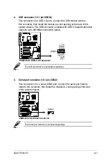
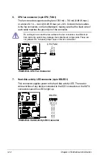
2. ICH7R Primary IDE connector (40-1 pin PRI_IDE1)
The onboard IDE connector is for the Ultra DMA 133/100 signal cable. There
are three connectors on each Ultra DMA 133/100 signal cable: blue, black,
and gray. Connect the blue connector to the motherboard’s IDE connector,
then select one of the following modes to configure your device.
®
P5BP-E/4L
P5BP-E/4L IDE Connector
NOTE:
Orient the red markings
(usually zigzag) on the ID
E
ribbon cable to PIN 1.
PRI_IDE1
PI
N
1
• Pin 20 on the IDE connector is removed to match the covered hole on
the Ultra ATA cable connector. This prevents incorrect insertion when you
connect the IDE cable.
• Use the 80-conductor IDE cable for Ultra ATA 100/66/33 IDE devices.
Drive jumper setting
Mode of
device(s)
Cable connector
Single device
Cable-Select or Master
-
Black
Two devices
Cable-Select
Master
Black
Slave
Gray
Master
Master
Black or gray
Slave
Slave
If any device jumper is set as “Cable-Select,” make sure all other device
jumpers have the same setting.
Содержание TS300-E5
Страница 1: ...TS300 E5 Intel Xeon 3000 3200 Series LGA775 Pedestal 5U Server ...
Страница 12: ...xii ...
Страница 76: ...Chapter 3 Installation option 3 10 ...
Страница 126: ...5 34 Chapter 5 BIOS setup ...
Страница 186: ...6 60 Chapter 6 RAID configuration ...
Страница 214: ...7 28 Chapter 7 Driver installation ...


