


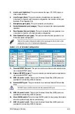


Drive jumper setting
Mode of
device(s)
Cable connector
Single device
Cable-Select or Master
-
Black
Two devices
Cable-Select
Master
Black
Slave
Gray
Master
Master
Black or gray
Slave
Slave
• Pin 20 on the IDE connector is removed to match the covered hole on the
Ultra DMA cable connector. This prevents incorrect insertion when you
connect the IDE cable.
• Use the 80-conductor IDE cable for Ultra DMA 133/100/66 IDE devices.
If any device jumper is set as “Cable-Select,” make sure all other device
jumpers have the same setting.
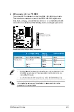
2. IDE connector (40-1 pin PRI_EIDE)
The onboard IDE connector is for the Ultra DMA 133/100/66 signal cable.
There are three connectors on each Ultra DMA 133/100/66 signal cable:
blue, black, and gray. Connect the blue connector to the motherboard’s IDE
connector, then select one of the following modes to configure your device.
ROG Rampage II Extreme
2-31
Содержание Rampage II Extreme
Страница 1: ...Motherboard Rampage II Extreme ...
Страница 16: ...ROG Rampage II Extreme Chapter summary 1 1 1 Welcome 1 1 1 2 Package contents 1 1 1 3 Special features 1 2 ...
Страница 26: ...1 10 Chapter 1 Product Introduction ...
Страница 80: ...2 52 Chapter 2 Hardware information ...
Страница 178: ...ROG Rampage II Extreme Chapter summary 5 5 1 ATI CrossFireX technology 5 1 5 2 NVIDIA SLI technology 5 6 ...
Страница 190: ...5 12 Chapter 5 Multiple GPU technology support ...
Страница 191: ...A Appendix Debug code table The Appendix lists the debug code table for the LCD Poster ...
Страница 192: ...ROG Rampage II Extreme Chapter summary A Debug code table A 1 ...
Страница 196: ...A 4 Appendix Debug code table ...


