background image

ASUS P/I-P65UP8 User’s Manual

19

III. INSTALLATION

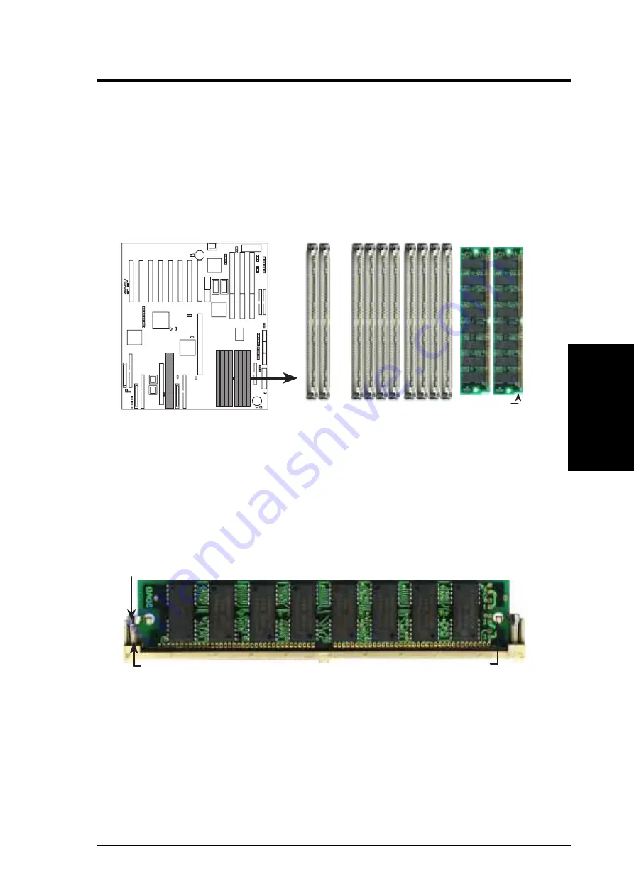
DRAM Memory Installation Procedures

IMPORTANT:  Install memory modules in symmetric pairs.

1. The SIMM memory modules will only fit in one orientation as shown because

of a “Plastic Safety Tab” on one end of the SIMM slots which requires the
“Notched End” of the SIMM memory modules.

R

72 Pin SIMM Sockets

5 6 7 8

1 2 3 4

2 1

Notched End

i960
Memory

System Memory

2. Press the memory module firmly into place starting from a 45 degree angle

making sure that all the contacts are aligned with the slot.

3. With your finger tips, rock the memory module into a vertical position so that it

clicks into place.

Clip

Plastic Safety Tab (This Side Only)

Mounting Hole

72 Pin DRAM in SIMM Socket

4. The plastic guides should go through the two mounting holes on the sides and

the clips should snap on the other side.

5. To release the memory module, squeeze both clips outward and rock the module

out of the clips.

(DRAM Memory)

III.  INST

ALLA

TION

Содержание P I-P65UP8 CP6ND

Страница 1: ...R P I P65UP8 Baseboard for CPU Cards USER S MANUAL ...

Страница 2: ...aring in this manual may or may not be registered trade marks or copyrights of their respective companies and are used only for identification or explanation and to the owners benefit without intent to infringe Intel LANDesk and Pentium are registered trademarks of Intel Corporation IBM and OS 2 are registered trademarks of International Business Machines Symbios is a registered trademark of Symbi...

Страница 3: ... com tw pub ASUS ASUS COMPUTER INTERNATIONAL Marketing Info Address 721 Charcot Avenue San Jose CA 95131 USA Telephone 1 408 474 0567 Fax 1 408 474 0568 Email info usa asus com tw Technical Support BBS 1 408 474 0569 Email tsd usa asus com tw WWW www asus com ASUS COMPUTER GmbH Marketing Info Address Harkort Str 25 40880 Ratingen BRD Germany Telephone 49 2102 445011 Fax 49 2102 442066 Email info g...

Страница 4: ...al Processing Unit 20 System Case 20 4 Expansion Cards 22 Expansion Card Installation Procedure 22 Assigning IRQs for Expansion Cards 22 Assigning DMA Channels for ISA Cards 23 5 External Connectors 24 IV VGA Installation 33 Windows 95 Video Driver Installation 33 Windows 95 Video Driver Installation 34 Using Control Panel 34 Windows 95 Display Settings 35 Windows NT 4 0 Video Driver Installation ...

Страница 5: ...ASUS P I P65UP8 User s Manual 5 This page was intentionally left blank ...

Страница 6: ...cular installation If this equipment does cause harmful interference to radio or television reception which can be determined by turning the equipment off and on the user is encouraged to try to correct the inter ference by one or more of the following measures Re orient or relocate the receiving antenna Increase the separation between the equipment and receiver Connect the equipment to an outlet ...

Страница 7: ...VGA Item Checklist Please check that your package is complete If you discover damaged or missing items please contact your retailer 1 ASUS Baseboard 1 9pin male serial 25pin male serial external connector set 1 25pin female parallel 6pin female PS 2 mouse external connector set 1 IDE ribbon cable for master and slave drives 1 Floppy ribbon cable for 1 5 25inch floppy and 2 3 5inch floppies 1 bag o...

Страница 8: ...t PCI slots Super Multi I O Provides two high speed UART compatible serial ports and one parallel port with EPP and ECP capabilities Supports two of either 5 25 or 3 5 inch disk drives 1 44MB or 2 88MB without an external card PCI Bus Master IDE Controller Comes with an onboard PCI Bus Master IDE controller with two connectors that supports four IDE devices in two chan nels supports PIO Modes 3 an...

Страница 9: ... 8 72 pin SIMM System Memory Sockets Intel i960RD I2O Expansion Slot Reserved for future 72 pin SIMM I2O Memory Sockets Onboard S3 VGA 3ISASlots OnboardVGA memory sockets ATX Power Connector AT Power Connector ATAux Pwr Connector Adaptec SCSI IDE 1 2 Connectors Parallel Serial Connectors Floppy Connector i960 NVRAM i960 Firmware Adaptec Single SCSI Channel Connectors Symbios Dual SCSI Channel Conn...

Страница 10: ... Socket 5 Bank 0 Parallel Port CR2032 3Volts Lithium Cell BIOS Power Floppy Drives JP1 Battery Test Secondary PCI Slot 3 Secondary PCI Slot 2 Secondary PCI Slot 4 SIMM Socket 2 Bank 1 SIMM Socket 1 Bank 0 HDLED B HDLED DRAMRAS 960SEL 7880IDSEL FS0 FS1 FS2 Infrared I2O Expansion Slot Reserved Main Power Input Server Conn ATX Power Input Intel Chipset R 1 35 34 68 1 35 34 68 1 35 34 68 Battery Con M...

Страница 11: ...rallel Port Connector 26 pin block 4 COM1 COM2 p 25 Serial Port Connectors 10 pin blocks 5 PRIMARYIDE SECONDARYIDE p 26 Primary SecondaryIDEConnectors 40 pinblocks 6 HD LED p 26 SCSI and IDEActivity LED 7 VGA Connector p 27 VGA Connector 16 pins 8 VGA Memory p 27 Two VGA Memory Expansion Sockets 9 IR p 28 SecondInfraredPortModuleConnector 5 pinblock 10 USB p 28 USB Module Connector 18 pin block 11...

Страница 12: ...connect pins 2 3 Jumpers with two pins will be shown as for short On and for open Off For manu facturing simplicity the jumpers may be sharing pins from other groups Use the diagrams in this manual instead of following the pin layout on the board Settings with two jumper numbers require that both jumpers be moved together To connect the pins simply place a plastic jumper cap over the two pins as d...

Страница 13: ...0SEL Setting I20 1 2 Bridge 2 3 R i960 Setting 3 2 1 I20 Bridge 960SEL 3 2 1 960SEL Caution The jumper numbering is reversed 2 i960 Local DRAM RAS Setting When the i960 is set to I20 the i960 chip acts as a processor and at least one SIMM memory module is required When using a single memory module this jumper does not need setting When using two memory modules this jumper needs to be set according...

Страница 14: ...ID Setting Set to SCSI ID 9 if you wish for the onboardAdpatec 7880 SCSI device to boot Set to SCSI ID 15 if you wish for the onboard Symbios 53C876 device to boot 7880IDSEL Setting ID 9 Boot 2 3 ID 15 No boot 1 2 R 7880 ID Setting SCSI ID 9 1 2 3 1 2 3 SCSI ID 15 7880IDSEL 7880IDSEL ...

Страница 15: ...OS setup to re enter user preferences Selections RTCLR Operation open Default Clear CMOS short momentarily RTC RAM Operation Open Default Clear CMOS Short R JP1 RTCLR Battery Test Remove jumper to test JP2 Battery Test 5 Battery Test Jumper JP1 JP2 You can test the battery s current by removing the jumper and attaching a cur rent meter to the two pins WARNING You must unplug the power cord to your...

Страница 16: ...S2 Jumper settings on CPU Card Settings on Baseboard Intel Pentium Pro P6 Processor Chipset Freq CPU Ext Freq CPU BUS CPU Card BUS Ratio on CPU Card Ext on Baseboard Internal Ratio JP13 JP14 JP15 JP16 JP6 JP7 Freq FS2 FS1 FS0 200MHz 3 0x ON ON ON ON 66MHz 180MHz 3 0x ON ON ON ON 60MHz ON 166MHz 2 5x ON ON ON ON 66MHz 150MHz 2 5x ON ON ON ON 60MHz ON Intel Pentium II Processor CPU Ext Freq CPU BUS ...

Страница 17: ...ASUS P I P65UP8 User s Manual 17 III INSTALLATION Jumpers III INSTALLATION This page was intentionally left blank ...

Страница 18: ...rs Install memory in any or all of the banks in any combination as follows Bank Memory Module Total Memory Bank 0 4 8 16 32 64 128MB x2 SIMM Slots 1 2 72 pin FPM EDO BEDO SIMM Bank 1 4 8 16 32 64 128MB x2 SIMM Slots 3 4 72 pin FPM EDO BEDO SIMM Bank 2 4 8 16 32 64 128MB x2 SIMM Slots 5 6 72 pin FPM EDO BEDO SIMM Bank 3 4 8 16 32 64 128MB x2 SIMM Slots 7 8 72 pin FPM EDO BEDO SIMM Total System Memo...

Страница 19: ...60 Memory System Memory 2 Press the memory module firmly into place starting from a 45 degree angle making sure that all the contacts are aligned with the slot 3 With your finger tips rock the memory module into a vertical position so that it clicks into place Clip Plastic Safety Tab This Side Only Mounting Hole 72 Pin DRAM in SIMM Socket 4 The plastic guides should go through the two mounting hol...

Страница 20: ...ows III INSTALLATION III INSTALLATION CPU Card 5 12 7 cm 12 2 30 7 cm Pentium II Processor Secondary PCI 4 Long Card Secondary PCI 3 Long Card Secondary PCI 1 Short Card PCI 3 Short Expansion Card PCI 2 Long Expansion Card PCI 1 Long Expansion Card System Cabinet Clearance Area Requirement for the P I P65UP8 CPU Card PS 2 Mouse PS 2 Keyboard Secondary PCI 2 Long Card ISA 3 Expansion Card ISA 2 Exp...

Страница 21: ... on installing the processor s sup port bracket and setting jumpers 3 Remove the expansion slot cover for the first slot 4 Carefully align the CPU card over the CPU Card Slot CPU SLOTAand CPU SLOT B 5 Be sure that the card is perpendicular to the baseboard Firmly press one end of the card halfway in the other end halfway in then the first end completely in and finally the second end completely in ...

Страница 22: ...ctors and press firmly 6 Secure the card on the slot with the screw you removed in step 4 7 Replace the computer system s cover 8 Set up the BIOS if necessary such as IRQ xx Used By ISA Yes in PNPAND PCI SETUP 9 Install the necessary software drivers for your expansion card Assigning IRQs for Expansion Cards IMPORTANT Interrupt requests are shared as shown by the following table INT A INT B INT C ...

Страница 23: ...ch was developed to allow automatic system configuration whenever a PnP compliant card is added to the system For PnP cards IRQs are assigned auto matically from those available If the system has both legacy and PnP ISA cards installed IRQs are assigned to PnP cards from those not used by legacy cards The PCI and PNP configuration section of the BIOS setup utility can be used to assign which IRQs ...

Страница 24: ...ctor on the baseboard or PS 2 keyboard connector on the CPU card Connector Plug from Keyboard Keyboard Connector 5 pin female Keyboard Connector PS 2 Keyboard Port CPU Card R PS 2 Mouse Port CPU Card 2 Floppy Disk Drive Connector 34 1 pin FLOPPY This connector supports the provided floppy drive ribbon cable After connect ing the single end to the board connect the two plugs on the other end to the...

Страница 25: ...lso remove the bracket connectors and mount them directly to the case to save expansion slot space R Pin 1 4 Serial Port COM1 and COM2 Connectors Two 10 1 pin COM1 COM2 These connectors support the provided serial port ribbon cables with mounting bracket Connect the ribbon cables to these connectors and mount the bracket to the case on an open slot You can make available the serial port and choose...

Страница 26: ... hard drive bootup see HDD Sequence SCSI IDE First in the BIOS FEA TURES SETUP of the BIOS software Pin 20 is removed to prevent insert ing in the wrong orientation when using ribbon cables with pin 20 plugged Primary IDE Connector Secondary IDE Connector IDE Hard Disk Drive Connectors Orient the red stripe on the IDE ribbon cable to Pin 1 R Pin 1 6 SCSI and IDE Activity LED 2 pin HD LED This conn...

Страница 27: ...lso remove the bracket connectors and mount them directly to the case to save expansion slot space 8 VGA Memory Upgrade Sockets This baseboard comes with 1MB VGA memory Two sockets are provided to upgrade the VGA memory to 2MB by adding two EDO DRAM s R VGA Memory Sockets Small indentation on the chip s sloped edge Socket s cut corner Each chip is 512KB DRAM Two chips must be installed to increase...

Страница 28: ... the baseboard according to the pin definitions The ribbon cable that may be supplied may either have five or ten pins for other standards If using a ten pin ribbon cable use only the top five row of the ribbon cable plug Infrared Module Connector For the infrared feature to be available connect an infrared module optional to the baseboard 5V IRTX IRRX NC GND Back View Front View IRRX 5V IRTX NC G...

Страница 29: ...connector is for an optional ASUS System Monitoring Module for moni toring chassis open close status A high level signal to the chassis signal lead will indicate to the system that the chassis has been opened R Chassis Connector For the chassis open alarm feature to work you must connect the optionalASUS Server Managment Module to these pins The 5V power comes from the power supply when the A C is...

Страница 30: ...ble 14 ATX Power Switch Soft Power Switch PWR SW ATX Power Req The system power can be controlled by a momentary switch connected to this lead Pushing the button once will switch the system between ON and OFF The system power LED shows the status of the system s power 15 Reset Switch Lead RESET This 2 pin connector connects to the case mounted reset switch for rebooting your computer without havin...

Страница 31: ...tion Example Up to 15 devices can be connected on each channel using either 50 Pin Fast SCSI and or 68 Pin Ultra Wide SCSI connections Three channels are provided on this motherboard SCSI devices in between must not be terminated Last SCSI device on the SCSI cable must be terminated 50 pin SCSI device 50 pin SCSI device end 68 pin SCSI device 68 pin SCSI device end SCSI device connection on one ch...

Страница 32: ...5Volts 5Volts Ground Ground 5Volts 5Volts RED RED RED BLK BLK BLK Using a slight angle align the plastic guide pins on the lead to their receptacles on the connector Once aligned press the lead onto the connector until the lead locks into place 21 ATX Power Supply Connector 20 pin ATXPWR This connector connects to a ATX power supply The plug from the power supply will only insert in one orientatio...

Страница 33: ... for the first time a New Hardware Found window will appear 1 Click OK to use the default selection Driver from disk provided by hard ware manufacturer 2 Insert ASUS support CD and click Browse button Open window appears 3 Select your CD ROM drive in the Drives box 4 Select VGA WIN95 5 Click the OK button Install from Disk appears Click OK button again 6 After restarting Windows your S3 Trio64 gra...

Страница 34: ...splay Type 4 Click Change 5 Click Have Disk Insert the ASUS support CD Type D VGA WIN95 as suming your CD ROM drive is letter D or click Browse button to select the path of the display driver for Windows 95 Click OK You will see a list of ASUS VGA devices Select the appropriate VGA device and press OK to start installation 6 When all files are copied return to Display Properties window by clicking...

Страница 35: ... in the Control Panel Click the appropriate Tab as follows Change Refresh Rate Adjustment Lets you change your monitor settings such as position size refresh rate and per formance Adjust display size Adjust display position Set to default values Adjust performance Change refresh rate Current virtual desk top screen and color List of refresh rate options Delete from list Test customized refresh rat...

Страница 36: ...ual desktop color palette and font size Hotkey Allows you to assign hotkeys in the Value box to move your screen up down left and right or zoom in zoom out in virtual desktop Adjust color Adjust font size List of hotkey options Hotkey enabled Highest performance Adjust virtual desktop size Adjust screen resolution Current refresh rate Set to default hotkey values Value Description Lowest performan...

Страница 37: ...Select Display Type 5 Select Change from the display options 6 Select Have Disk 7 Windows NT will prompt you for the correct path enter the path of driver in CD ROM such as D VGA NT40 assuming your CD ROM drive is letter D 8 A list of ASUS S3 series video adapters will be displayed Select the one you are using then click on the OK button 9 Windows NT will once again prompt for confirmation All app...

Страница 38: ...port CD into your CD ROM drive For Windows NT 3 51 type the following D VGA NT351 assuming your CD ROM drive is letter D 9 Click OK button 10 Select S3 driver 11 Click Install 12 Click Yes to change your system configuration 13 Click Continue to confirm the full path name 14 After the files have been copied to your computer click OK 15 Reboot Windows NT 16 After reboot the Invalid Display Settings...

Страница 39: ...ears 9 Restart OS 2 It will default to 640x480 in 256 colors To change screen resolu tion and or color depth see your OS 2 User s Guide AutoCAD Video Driver Installation 1 Enter DOS mode 2 Insert the ASUS support CD assuming your CD ROM drive is letter D 3 Change current directory to D DOS AutoCAD type INSTALL Enter 4 Follow the instructions to complete the installation of the drivers Type direc t...

Страница 40: ...40 ASUS P I P65UP8 User s Manual IV VGA Installation This page was intentionally left blank ...

Отзывы: