background image

1-

Chapter 1: Product introduction

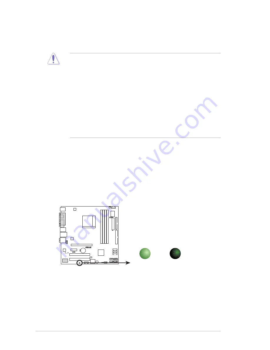
Onboard LED

The motherboard comes with a standby power LED. The green LED lights up 

to indicate that the system is ON, in sleep mode, or in soft-off mode. This is a 

reminder that you should shut down the system and unplug the power cable 

before removing or plugging in any motherboard component. The illustration 

below shows the location of the onboard LED.

1.3 

Before you proceed

Take note of the following precautions before you install motherboard components 

or change any motherboard settings.

•  Unplug the power cord from the wall socket before touching any  

component.

•  Use a grounded wrist strap or touch  a safely grounded object or to  

a metal object, such as the power supply case, before handling 

components to avoid damaging them due to static electricity.

•  Hold components by the edges to avoid touching the ICs on them.
•  Whenever you uninstall any component, place it on a grounded  

antistatic pad or in the bag that came with the component.

•  Before you install or remove any component, ensure 

that the ATX power supply is switched off or the power cord is detached 

from the power supply. Failure to do so may cause severe damage to the 

motherboard, peripherals, and/or components.

M2NS-NVM

®

M2NS-NVM Onboard LED

SB_PWR1

ON

Standby

Power

OFF

Powered

Off

Содержание M2NS-NVM

Страница 1: ...Motherboard M2NS NVM ...

Страница 2: ...ERCHANTABILITY OR FITNESS FOR A PARTICULAR PURPOSE IN NO EVENT SHALL ASUS ITS DIRECTORS OFFICERS EMPLOYEES OR AGENTS BE LIABLE FOR ANY INDIRECT SPECIAL INCIDENTAL OR CONSEQUENTIAL DAMAGES INCLUDING DAMAGES FOR LOSS OF PROFITS LOSS OF BUSINESS LOSS OF USE OR DATA INTERRUPTION OF BUSINESS AND THE LIKE EVEN IF ASUS HAS BEEN ADVISED OF THE POSSIBILITY OF SUCH DAMAGES ARISING FROM ANY DEFECT OR ERROR I...

Страница 3: ...1 5 2 Installing the heatsink and fan 1 9 1 6 System memory 1 12 1 6 1 DIMM socket location 1 12 2 4 2 Memory configurations 1 13 1 6 3 Installing a DIMM 1 14 1 6 4 Removing a DIMM 1 14 1 7 Expansion slots 1 15 1 7 1 Installing an expansion card 1 15 1 7 2 Configuring an expansion card 1 15 1 7 3 Interrupt assignments 1 16 1 7 4 PCI slots 1 17 1 7 5 PCI Express x1 slot 1 17 1 7 6 PCI Express x16 s...

Страница 4: ... help 2 12 2 3 Main menu 2 13 2 3 1 System Time 2 13 2 3 2 System Date 2 13 2 3 3 Primary IDE Master Slave 2 14 2 3 4 SATA1 2 2 16 2 4 Advanced menu 2 20 2 4 1 Onboard Device Configuration 2 20 2 4 2 PCIPnP 2 23 2 4 3 Event Log Configuration 2 24 2 5 Power menu 2 25 2 5 1 APM Configuration 2 26 2 5 2 Hardware Monitor 2 28 2 5 3 ACPI APIC Support 2 29 2 5 4 Cool N Quiet 2 29 2 6 Boot menu 2 28 2 6 ...

Страница 5: ...use harmful interference to radio or television reception which can be determined by turning the equipment off and on the user is encouraged to try to correct the interference by one or more of the following measures Reorient or relocate the receiving antenna Increase the separation between the equipment and receiver Connect the equipment to an outlet on a circuit different from that to which the ...

Страница 6: ...your area If you are not sure about the voltage of the electrical outlet you are using contact your local power company If the power supply is broken do not try to fix it by yourself Contact a qualified service technician or your retailer Operation safety Before installing the motherboard and adding devices on it carefully read all the manuals that came with the package Before using the product ma...

Страница 7: ...A VT6308 1394a connectors Optional USB MCP61S support 8 USB ports Rear panel 1 x PS 2 keyboard port purple 1 x PS 2 mouse port green 1 x VGA port 1 x Coaxial S PDIF Out port 1 x LAN RJ 45 port 4 x USB 2 0 1 1 ports 1 x Coaxial S PDIF Out optional 8 channel audio ports Internal connectors 2 x USB 2 0 connectors support four additional USB 2 0 ports 1 x Primary IDE connector 2 x Serial ATA connector...

Страница 8: ...viii ...

Страница 9: ... meet the higher bandwidth requirements of the latest 3D graphics multimedia and Internet applications The dual channel DDR2 architecture doubles the bandwidth of your system memory to boost system performance eliminating bottlenecks with peak bandwidths of up to 10 7 GB s See pages 2 12 to 2 13 for details PCI Express interface The motherboard fully supports PCI Express the latest I O interconnec...

Страница 10: ...ology through the S PDIF interfaces on the rear panel The S PDIF technology turns your computer into a high end entertainment system with digital connectivity to powerful audio and speaker systems See page 2 27 for details USB 2 0 technology The motherboard implements the Universal Serial Bus USB 2 0 specification dramatically increasing the connection speed from the 12 Mbps bandwidth on USB 1 1 t...

Страница 11: ...tails ASUS EZ Flash EZ Flash is a user friendly BIOS update utility Simply press the predefined hotkey to launch the utility and update the BIOS without entering the OS Update your BIOS easily without preparing a bootable diskette or using an OS based flash utility See pages 4 5 and 4 47 for details ASUS Q Fan 2 technology The ASUS Q Fan 2 technology smartly adjusts the fan speeds according to the...

Страница 12: ... power cord from the wall socket before touching any component Use a grounded wrist strap or touch a safely grounded object or to a metal object such as the power supply case before handling components to avoid damaging them due to static electricity Hold components by the edges to avoid touching the ICs on them Whenever you uninstall any component place it on a grounded antistatic pad or in the b...

Страница 13: ...B12 IE1394_2 FLOPPY1 Super I O 4Mb BIOS PS 2KBMS T Mouse B Keyboard LAN_USB34 CD1 PCIEX16 PCIEX1_1 PCI1 PCI2 CLRTC1 USB910 USB78 SYS_FAN1 ATX12V1 SB_PWR1 SPDIF_OUT2 nVIDIA MCP61S EATXPWR1 F_PANEL1 CPU_FAN1 ALC888 PARALLEL PORT VGA1 SPDIF_O1 DDR2 DIMM_B1 64 bit 240 pin module DDR2 DIMM_A2 64 bit 240 pin module DDR2 DIMM_B2 64 bit 240 pin module RTL8201CL VT6308 SATA1 SATA2 SATA3 SATA4 USB56 BUZZER1...

Страница 14: ...he correct orientation The edge with external ports goes to the rear part of the chassis as indicated in the image below 1 4 3 Screw holes Place eight 8 screws into the holes indicated by circles to secure the motherboard to the chassis Place this side towards the rear of the chassis Do not overtighten the screws Doing so can damage the motherboard ...

Страница 15: ...5 Central Processing Unit CPU The motherboard comes with a 940 pin AM2 socket designed for the AMD Athlon 64 X2 Athlon 64 Sempron processor Socket lever The AM2 socket has a different pinout from the 939 pin socket designed for the AMD Opteron processor Make sure you use a CPU is designed for the AM2 socket The CPU fits in only one correct orientation DO NOT force the CPU into the socket to preven...

Страница 16: ...ith a small triangle 4 Carefully insert the CPU into the socket until it fits in place 5 When the CPU is in place push down the socket lever to secure the CPU The lever clicks on the side tab to indicate that it is locked 6 Install a CPU heatsink and fan following the instructions that came with the heatsink package Gold triangle Small triangle ...

Страница 17: ...eatsink and fan assembly should come with installation instructions for the CPU heatsink and the retention mechanism If the instructions in this section do not match the CPU documentation follow the latter The retention module base is already installed on the motherboard upon purchase You do not have to remove the retention module base when installing the CPU or installing other motherboard compon...

Страница 18: ...bracket lock to the retention module base A clicking sound denotes that the retention bracket is in place 4 Push down the retention bracket lock on the retention mechanism to secure the heatsink and fan to the module base Make sure that the fan and heatsink assembly perfectly fits the retention mechanism module base otherwise you cannot snap the retention bracket in place ...

Страница 19: ...lace connect the CPU fan cable to the connector on the motherboard labeled CPU_FAN1 Do not forget to connect the CPU fan connector Hardware monitoring errors can occur if you fail to plug this connector M2NS NVM M2NS NVM CPU fan connector GND Rotation 12V CPU_FAN1 ...

Страница 20: ...the same physical dimensions as a DDR DIMM but has a 240 pin footprint compared to the 184 pin DDR DIMM DDR2 DIMMs are notched differently to prevent installation on a DDR DIMM socket The figure illustrates the location of the DDR2 DIMM sockets Channel Sockets Channel 1 DIMM_A1 and DIMM_B1 Channel 2 DIMM_A2 and DIMM_B2 M2NS NVM M2NS NVM 240 pin DDR2 DIMM sockets DIMM_A1 DIMM_B1 DIMM_A2 DIMM_B2 ...

Страница 21: ...as shown then click Search Click the article titled 4GB memory installed but less memory size detected You also may check the URLs below for third party comments on this issue http dlsvr01 asus com pub ASUS mb 4GB_Rev1 pdf http www intel com support motherboards server sb cs 016594 htm For dual channel configuration the total size of memory module s installed per channel must be the same DIMM_A1 D...

Страница 22: ...the retaining clips snap back in place and the DIMM is properly seated 1 6 4 Removing a DIMM To remove a DIMM 1 Simultaneously press the retaining clips outward to unlock the DIMM 2 Remove the DIMM from the socket A DDR2 DIMM is keyed with a notch so that it fits in only one direction Do not force a DIMM into a socket to avoid damaging the DIMM The DDR2 DIMM sockets do not support DDR DIMMs DO not...

Страница 23: ...n the slot 5 Secure the card to the chassis with the screw you removed earlier 6 Replace the system cover 1 7 2 Configuring an expansion card After installing the expansion card configure the it by adjusting the software settings 1 Turn on the system and change the necessary BIOS settings if any See Chapter 4 for information on BIOS setup 2 Assign an IRQ to the card Refer to the tables on the next...

Страница 24: ...1 2 Keyboard Controller 2 Redirect to IRQ 9 4 12 Communications Port COM1 5 13 IRQ Holder for PCI Steering 6 14 Floppy Disk Controller 7 15 Printer Port LPT1 8 3 System CMOS Real Time Clock 9 4 IRQ Holder for PCI Steering 10 5 IRQ Holder for PCI Steering 11 6 IRQ Holder for PCI Steering 12 7 PS 2 Compatible Mouse Port 13 8 Numeric Data Processor 14 9 Primary IDE Channel 15 10 Secondary IDE Channel...

Страница 25: ...I Express x1 slot This motherboard supports PCI Express x1 network cards SCSI cards and other cards that comply with the PCI Express specifications The figure shows a network card installed on the PCI Express x1 slot 1 7 6 PCI Express x16 slot This motherboard supports PCI Express x16 graphic cards that comply with PCI Express specifications The figure shows a graphics card installed on the PCI Ex...

Страница 26: ...the power cord 2 Remove the onboard battery 3 Move the jumper cap from pins 1 2 default to pins 2 3 Keep the cap on pins 2 3 for about 5 10 seconds then move the cap back to pins 1 2 4 Reinstall the battery 5 Plug the power cord and turn ON the computer 6 Hold down the Del key during the boot process and enter BIOS setup to re enter data Except when clearing the RTC RAM never remove the cap on CLR...

Страница 27: ...ort connects a microphone 9 Side Speaker Out port gray This port connects the side speakers in an 8 channel audio configuration Activity Link Speed LED Status Description Status Description OFF No link OFF 10 Mbps connection ORANGE Linked ORANGE 100 Mbps connection BLINKING Data activity GREEN 1 Gbps connection LAN port LED indications SPEED LED ACT LINK LED LAN port 1 14 10 2 3 11 5 4 6 7 8 9 12 ...

Страница 28: ...ut Black Rear Speaker Out Rear Speaker Out Rear Speaker Out Orange Center Subwoofer Center Subwoofer 10 USB 2 0 ports 3 and 4 These two 4 pin Universal Serial Bus USB ports are available for connecting USB 2 0 devices 11 USB 2 0 ports 1 and 2 These two 4 pin Universal Serial Bus USB ports are available for connecting USB 2 0 devices 12 Video Graphics Adapter VGA port This port is for a VGA monitor...

Страница 29: ...nsert one end of the cable to this connector then connect the other end to the signal connector at the back of the floppy disk drive Pin 5 on the connector is removed to prevent incorrect cable connection when using a FDD cable with a covered Pin 5 M2NS NVM M2NS NVM Floppy disk drive connector NOTE Orient the red markings on the floppy ribbon cable to PIN 1 PIN 1 FLOPPY ...

Страница 30: ...o match the covered hole on the Ultra DMA cable connector This prevents incorrect insertion when you connect the IDE cable Use the 80 conductor IDE cable for Ultra DMA 100 66 IDE devices If any device jumper is set as Cable Select make sure all other device jumpers have the same setting Drive jumper setting Mode of device s Cable connector Single device Cable Select or Master Black Two devices Cab...

Страница 31: ... cables for Serial ATA 3 0 Gb s hard disk and optical disk drives The Serial ATA 3 0 Gb s is backward compatible with Serial ATA 1 5 Gb s specification M2NS NVM M2NS NVM SATA connectors GND RSATA_TXP1 RSATA_TXN1 GND RSATA_RXP1 RSATA_RXN1 GND SATA1 GND RSATA_TXP2 RSATA_TXN2 GND RSATA_RXP2 RSATA_RXN2 GND SATA2 ...

Страница 32: ...ing so will damage the motherboard 5 IEEE 1394a port connector 10 1 pin IE1394_2 Optional This connector is for an IEEE 1394a port Connect the IEEE 1394a module cable to the connector then install the module to a slot opening at the back of the system chassis Never connect a USB cable to the IEEE 1394a connector Doing so will damage the motherboard M2NS NVM USB 5V USB_P6 USB_P6 GND NC M2NS NVM USB...

Страница 33: ...connectors on the motherboard making sure that the black wire of each cable matches the ground pin of the connector Do not forget to connect the fan cables to the fan connectors Insufficient air flow inside the system may damage the motherboard components These are not jumpers Do not place jumper caps on the fan connectors M2NS NVM M2NS NVM Fan connectors SYS_FAN1 GND Rotation 12V CPU_FAN1 GND Rot...

Страница 34: ...connectors EATXPWR1 ATX12V1 3 Volts 3 Volts Ground 5 Volts 5 Volts Ground Ground Power OK 5V Standby 12 Volts 5 Volts 5 Volts 3 Volts 12 Volts Ground Ground Ground PSON Ground 5 Volts 12 Volts 3 Volts 5 Volts Ground 12V DC GND 12V DC GND M2NS NVM M2NS NVM Digital audio connector 5V SPDIFOUT GND SPDIF_OUT2 7 Digital Audio connector 4 1 pin SPDIF_OUT2 Optional This connector is for the S PDIF audio ...

Страница 35: ... inadequate 9 Front panel audio connector 10 1 pin AAFP This connector is for a chassis mounted front panel audio I O module that supports either HD Audio or legacy AC 97 audio standard Connect one end of the front panel audio I O module cable to this connector We recommend that you connect a high definition front panel audio module to this connector to avail of the motherboard s high definition a...

Страница 36: ... MPEG card 11 Serial port connector 10 1 pin COM2 Optional This connector is for a serial COM port Connect the serial port module cable to this connector then install the module to a slot opening at the back of the system chassis M2NS NVM M2NS NVM Internal audio connector CD1 black Right Audio Channel Left Audio Channel Ground Ground M2NS NVM M2NS NVM COM port connector PIN 1 COM2 ...

Страница 37: ... ATX power button soft off button 2 pin PWR_BTN This 2 pin connector is for the system power button Pressing the power button turns the system on or puts the system in sleep or soft off mode depending on the BIOS settings Pressing the power switch for more than four seconds while the system is ON turns the system OFF Reset button 2 pin RESET This 2 pin connector is for the chassis mounted reset bu...

Страница 38: ...1 30 Chapter 1 Product introduction ...

Страница 39: ... Award BIOS Flash Utility Updates the BIOS in DOS mode using a bootable floppy disk 4 ASUS CrashFree BIOS 2 Updates the BIOS using a bootable floppy disk or the motherboard support CD when the BIOS file fails or gets corrupted Refer to the corresponding sections for details on these utilities Save a copy of the original motherboard BIOS file to a bootable floppy disk in case you need to restore th...

Страница 40: ... Click File from the menu then select Format A Format 3 1 2 Floppy Disk window appears e Select Create an MS DOS startup disk from the format options field then click Start Windows 2000 environment To create a set of boot disks for Windows 2000 a Insert a formatted high density 1 44 MB floppy disk into the drive b Insert the Windows 2000 CD to the optical drive c Click Start then select Run d From...

Страница 41: ...OST to display the following EZFlash starting BIOS update Checking for floppy 4 Insert the floppy disk that contains the BIOS file to the floppy disk drive When the correct BIOS file is found EZ Flash performs the BIOS update process and automatically reboots the system when done EZFlash starting BIOS update Checking for floppy Floppy found Reading file A8R32 MVP ROM Completed Start erasing Start ...

Страница 42: ...table floppy disk CD ROM or a USB flash disk you created earlier 4 Under the DOS mode use X X stands for the name of the disk assignment to switch to the folder of floppy disk CD ROM or USB flash disk you saved the BIOS file and Award BIOS Flash Utility 5 At the prompt type awdflash then press Enter The Award BIOS Flash Utility screen appears AwardBIOS Flash Utility for ASUS V1 14 C Phoenix Techno...

Страница 43: ... Reset System 9 The utility displays a Flashing Complete message indicating that you have successfully flashed the BIOS file Remove the floppy disk then press F1 to restart the system AwardBIOS Flash Utility for ASUS V1 14 C Phoenix Technologies Ltd All Rights Reserved F1 Reset For C51XEMCP55PXE M2N32 WS 00 DATE 04 13 2006 Flash Type Unknown Flash File Name to Program 0107 bin Flashing Complete Pr...

Страница 44: ...ashing process AwardBIOS Flash Utility for ASUS V1 14 C Phoenix Technologies Ltd All Rights Reserved Message For C51XEMCP55PXE M2N32 WS 00 DATE 04 13 2006 Flash Type Unknown Flash File Name to Program 0107 bin Save current BIOS as AwardBIOS Flash Utility for ASUS V1 14 C Phoenix Technologies Ltd All Rights Reserved Message Please Wait For C51XEMCP55PXE M2N32 WS 00 DATE 04 13 2006 Flash Type Unknow...

Страница 45: ...at allows you to restore the BIOS file when it fails or gets corrupted during the updating process You can update a corrupted BIOS file using the motherboard support CD or the floppy disk that contains the updated BIOS file Recovering the BIOS from a floppy disk To recover the BIOS from a floppy disk 1 Turn on the system 2 Insert the floppy disk with the original or updated BIOS file to the floppy...

Страница 46: ... Checking for CD ROM CD ROM found Reading file A8R32 MVP ROM Completed Start flashing When no floppy disk is found the utility automatically checks the optical drive for the original or updated BIOS file The utility then updates the corrupted BIOS file Bad BIOS checksum Starting BIOS recovery Checking for floppy The recovered BIOS may not be the latest BIOS version for this motherboard Visit the A...

Страница 47: ...ess Del during the Power On Self Test POST to enter the Setup utility otherwise POST continues with its test routines If you wish to enter Setup after POST restart the system by pressing Ctrl Alt Delete or by pressing the reset button on the system chassis You can also restart by turning the system off and then back on Do this last option only if the first two failed The Setup program is designed ...

Страница 48: ...NS NVM 0104 Base Memory 640K Extended Memory 478MB Memory Channel Single Channel Memory Speed DDR2 533 MHz CPUID OFF2 2 2 2 Menu bar The menu bar on top of the screen has the following main items Main For changing the basic system configuration Advanced For changing the advanced system settings Power For changing the advanced power management APM configuration Boot For changing the system boot con...

Страница 49: ...ghted when selected To change the value of a field select it then press Enter to display a list of options Refer to 4 2 7 Pop up window 2 2 3 Legend bar At the bottom of the Setup screen is a legend bar The keys in the legend bar allow you to navigate through the various setup menus The following table lists the keys found in the legend bar with their corresponding functions Navigation Key Functio...

Страница 50: ...al size of diskette drive A System Time 15 30 36 System Date Tue Aug 29 2006 Legacy Diskette A 1 44M 3 5 in Primary IDE Master ST321122A Primary IDE Slave ASUS CDS520 A SATA 1 SATA 2 CPU Type AMD Sempron tm Processor 3400 CPU Speed 1810MHz Hyper Transport Speed 800MHz BIOS Version M2NS NVM 0104 Base Memory 640K Extended Memory 478MB Memory Channel Single Channel Memory Speed DDR2 533 MHz CPUID OFF...

Страница 51: ...PU Type AMD Sempron tm Processor 3400 CPU Speed 1810MHz Hyper Transport Speed 800MHz BIOS Version M2NS NVM 0104 Base Memory 640K Extended Memory 478MB Memory Channel Single Channel Memory Speed DDR2 533 MHz CPUID OFF2 2 3 Main menu When you enter the BIOS Setup program the Main menu screen appears giving you an overview of the basic system information Refer to section 2 2 1 BIOS menu screen for in...

Страница 52: ...E Master Slave Auto Select Auto to automatically detect an IDE hard disk drive If automatic detection is successful the BIOS automatically fills in the correct values for the remaining fields on this sub menu If the hard disk was already formatted on a previous system the setup BIOS may detect incorrect parameters Select Manual to manually enter the IDE hard disk drive parameters If no drive is in...

Страница 53: ...detection of an IDE hard disk drive Select CHS for this item if you set the IDE Primary Master Slave to Manual Configuration options CHS LBA Large Auto Before attempting to configure a hard disk drive make sure you have the correct configuration information supplied by the drive manufacturer Incorrect settings may cause the system to fail to recognize the installed hard disk After entering the IDE...

Страница 54: ... addressing mode Configuration options Large Auto F1 Help Select Item Change Value F5 Setup Defaults ESC Exit Select Menu Enter Select SubMenu F10 Save and Exit Phoenix Award BIOS CMOS Setup Utility Main Select Menu Item Specific Help Selects the type of fixed disk connected to the system SATA 1 Extended IDE Drive Auto Access Mode Auto Capacity 0 MB Cylinder 0 Head 0 Precomp 0 Landing Zone 0 Secto...

Страница 55: ...not configurable Sector Shows the number of sectors per track This item is not configurable After entering the IDE hard disk drive information into BIOS use a disk utility such as FDISK to partition and format new IDE hard disk drives This is necessary so that you can write or read data from the hard disk Make sure to set the partition of the Primary IDE hard disk drives to active ...

Страница 56: ...s Incorrect field values can cause the system to malfunction F1 Help Select Item Change Value F5 Setup Defaults ESC Exit Select Menu Enter Select SubMenu F10 Save and Exit F1 Help Select Item Change Value F5 Setup Defaults ESC Exit Select Menu Enter Select SubMenu F10 Save and Exit Select Menu Item Specific Help Press Enter to set IDE controller function Onboard Device Configuration IDE Function S...

Страница 57: ...on options Disabled Enabled SATA Controller SATA 1 Allows you to enable or disable the onboard SATA controller Configuration options Disabled SATA 1 IDE Prefetch Mode Enabled Allows you to enable or disable the IDE PIO read prefetch mode Configuration options Disabled Enabled Select Menu Item Specific Help Enable or Disable the USB 1 1 and 2 0 Controller USB Configuration USB Controller Enabled US...

Страница 58: ...d OnBoard Video Memory 32M Allows you to select or disable the VGA Share Memory Size Configuration options 16M 32M 64M 128M 256M Disabled HD Audio Enable Allows you to enable or disable the High Definition audio function Configuration options Enable Disabled Onboard LAN Enabled Allows you to enable or disable the onboard LAN controller Configuration options Enable Disabled Onboard LAN Boot ROM Ena...

Страница 59: ...nfiguration options Auto Manual The item IRQ Resources becomes user configurable when you set Resources Controlled By to Manual IRQ Resources IRQ Resources IRQ 5 assigned to PCI Device IRQ 7 assigned to PCI Device IRQ 9 assigned to PCI Device IRQ 10 assigned to PCI Device IRQ 11 assigned to PCI Device IRQ 14 assigned to PCI Device IRQ 15 assigned to PCI Device Phoenix Award BIOS CMOS Setup Utility...

Страница 60: ...DMI Event Log Enabled Clear All DMI Event Log Yes View DMI Event Log Enter Mark DMI Events as Read Enter Evenxt Log Capacity Space Available Event Log Validity Valid Phoenix Award BIOS CMOS Setup Utility Advanced 2 4 3 Event Log Configuration DMI Event Log Enabled Allows you to enable or disable logging of DMI events Configuration options Disabled Enabled Clear All DMI Event Log Yes Selecting Yes ...

Страница 61: ...Select an item then press Enter to display the configuration options Select Menu Item Specific Help Sleep timer Suspend timer F1 Help Select Item Change Value F5 Setup Defaults ESC Exit Select Menu Enter Select Sub menu F10 Save and Exit Phoenix Award BIOS CMOS Setup Utility Main Advanced Power Boot Exit APM Configuration Hardware Monitor ACPI APIC support Enabled Cool N Quiet Auto ...

Страница 62: ...em state on or off before the power interruption Configuration options System Off System On Former Sts Power Management User Define Allows you to set the automatic power saving features Configuration options User Define Min Saving Max Saving HDD Power Down Disabled Allows you to set the time out value for shutting down any IDE hard disk drives in the system after a period of inactivity Configurati...

Страница 63: ...ues Configuration options Disabled Enabled Date of Month Alarm Disabled To set the date of alarm highlight this item and press Enter to display the Date of Month Alarm pop up menu Key in a value within the specified range then press Enter Configuration options Min 0 Max 31 Time hh mm ss Alarm Disabled To set the time of alarm 1 Highlight this item and press Enter to display a pop up menu for the h...

Страница 64: ...PM The onboard hardware monitor automatically detects and displays the CPU and system fan speeds in rotations per minute RPM If any of the fans is not connected to the motherboard the field shows 0 These items are not user configurable Select Menu Item Specific Help Press Enter to enable or disable Hardware Monitor CPU Temperature 48ºC CPU Temperature offset 41ºC SIO Read Temperature 51ºC System T...

Страница 65: ...wer Interface ACPI support in the Application Specific Integrated Circuit ASIC When set to Enabled the ACPI APIC table pointer is included in the RSDT pointer list Configuration options Disabled Enabled 2 5 4 Cool N Quiet Enabled Enables or disables the AMD Cool n Quiet technology Configuration options Auto Disabled ...

Страница 66: ...Value F5 Setup Defaults ESC Exit Select Menu Enter Select Sub menu F10 Save and Exit 2 6 1 Boot Device Priority Select Menu Item Specific Help Select Your Boot Device Priority Boot Device Priority 1st Boot Device CDROM 2nd Boot Device Hard Disk 3rd Boot Device Network 4th Boot Device Removable Phoenix Award BIOS CMOS Setup Utility Boot 1st 4th Boot Device Removable These items specify the boot dev...

Страница 67: ... Priority 1 Network 0 xxxxxxxxxxxx Phoenix Award BIOS CMOS Setup Utility Boot 2 6 4 Boot Settings Configuration F1 Help Select Item Change Value F5 Setup Defaults ESC Exit Select Menu Enter Select Sub menu F10 Save and Exit Select Menu Item Specific Help Press Enter to enable or disable Boot Settings Configuration Recovery Boot Enabled Boot Virus Detection Disabled Quick Boot Enabled Bootup Num Lo...

Страница 68: ...the system When set to Yes and if you install a Plug and Play operating system the operating system configures the Plug and Play devices not required for boot Configuration options No Yes Full Screen LOGO Enabled Allows you to enable or disable the full screen logo display feature Configuration options Disabled Enabled Summary Screen Show Disabled Allows you to enable or disable the summary screen...

Страница 69: ...password field setting is changed to Set To clear the password 1 Select the password field and press Enter twice The following message appears PASSWORD DISABLED Press any key to continue 2 Press any key to continue The password field setting is changed to Clear A note about passwords The Supervisor password is required to enter the BIOS Setup program preventing unauthorized access The User passwor...

Страница 70: ...OS setup or the system Select Setup to require the password before entering the BIOS Setup Select System to require the password before entering the system Configuration options Setup System BIOS Write Protection Disabled Set the item to Disabled if you are updating BIOS Configuration options Disabled Enabled ...

Страница 71: ...Defaults Setting This option allows you to load the default values for each of the parameters on the Setup menus When you select this option or if you press F5 a confirmation window appears Select YES to load default values Select Save Exit Setup or make other changes before saving the values to the non volatile RAM Discard Changes This option allows you to discard the selections you made and rest...

Страница 72: ...2 34 Chapter 2 BIOS setup ...

Отзывы: