background image


STEP 1:   


Attach the 

Front Stabilizer (No. 18) 

and the 

Rear Stabilizer (No. 14)

 to the Main 

Frame (Y) using 4 

Bolts

 (No. 10)

, 4 

Washers

 (No. 9) 

and 4 

Nuts

 (No. 8)

. Tighten and 

secure using spanner wrench. 


Assembly Instruction 


Содержание 7150 Minotaur

Страница 1: ...Owner s Manual Made in Taiwan 7150 Minotaur Magnetic Commercial Indoor Cycling Bike...

Страница 2: ......

Страница 3: ...ase be sure to follow each step accordingly as it has been explained within this manual WARNING During assembly it is recommended that all bolts be tightened by hand Upon completing assembly bolts sho...

Страница 4: ...ult use only 4 Use the equipment on a solid flat level surface with a protective cover for your floor or carpet To ensure safety the equipment should have at least 2 feet 60cm of free space all around...

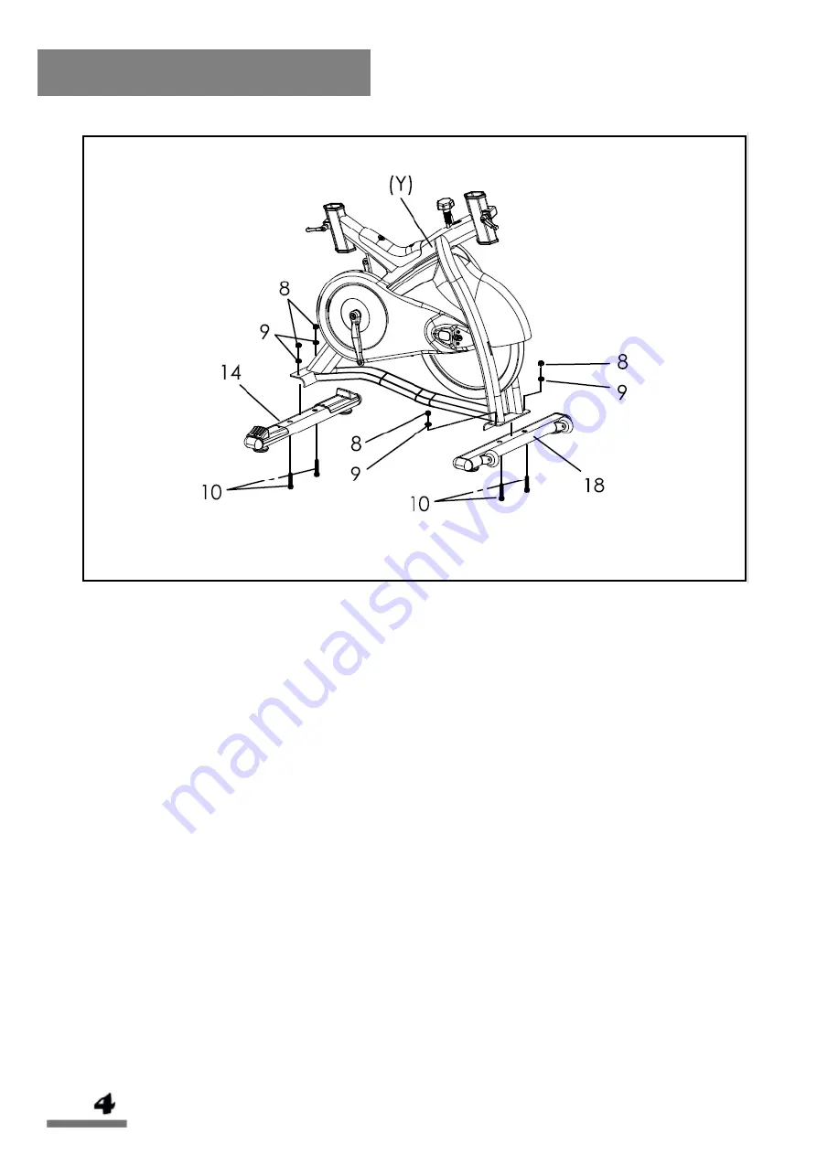
Страница 5: ...Exploded Drawing...

Страница 6: ...1 59 E clip w fixed pin 1 21 Right crank arm 1 60 Screw nut for brake pad 1 22 Handlebar post 1 61 Washer 4 23 Handlebar 1 62 Rubber cover for flywheel 2 24 Tension knob 1 63 Fixed plate for fender 1...

Страница 7: ...TEP 1 Attach the Front Stabilizer No 18 and the Rear Stabilizer No 14 to the Main Frame Y using 4 Bolts No 10 4 Washers No 9 and 4 Nuts No 8 Tighten and secure using spanner wrench Assembly Instructio...

Страница 8: ...dlebar Post No 22 to the desired height Tighten the L Shaped Knob 1 No 6 to secure the Handlebar Post No 22 into position Slide the Handlebar No 23 onto the Handlebar Post No 22 Tighten the L Shaped K...

Страница 9: ...42 Tighten the L Shaped Knob 1 No 6 to secure the Seat Slider No 43 in place Secure the Seat No 1 onto the post of the Seat Slider No 43 Tighten the seat clamp screw to secure the Seat No 1 in place U...

Страница 10: ...arm turn the pedal counter clockwise as tightly as you can with your hand Tighten and secure with 15mm spanner wrench Right Pedal align the right pedal Pedal R No 11 with the Right Crank Arm No 21 at...

Страница 11: ...Assembly is complete...

Страница 12: ...operational Inspect all screws nuts and bolts as well to make sure that they are tightened and secure MOVING There are Transportation Wheels No 39 on the front stabilizer Hold the handlebar and tilt...

Страница 13: ...Slide the handlebar assembly forwards and backwards until you reach the desired position Once adjusted retighten the L Shaped Knob 2 No 17 SEAT ADJUSTMENT To adjust the seat height loosen the L Shape...

Страница 14: ...way sweat and moisture after each use Inspect all nuts and bolts associated with moving parts of the equipment and tighten as required Check the mobility of moving parts and components on the equipmen...

Страница 15: ......

Страница 16: ......

Отзывы: