8
BHL Trim
Installation Instructions
8200 Series
A8131F 08/19
Copyright © 2019, SARGENT Manufacturing Company. All rights reserved. Reproduction in whole or
in part without the express written permission of SARGENT Manufacturing Company is prohibited.
1-800-727-5477 • www.sargentlock.com
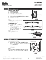
11. Turn-piece functions only: install turn-piece thru-bolt plate using truss head screw. (Leave screw
slightly loose.) (Figure 15)
12. Insert mortise lockbody into door and loosely tighten 1” lock
mounting combination screws.
NOTE:
Make sure lock is unlocked. (Figure 16)
7
BHL Trim Installation
1. Install strike using 3/4” strike mounting screws.
NOTE:
Strike must be oriented with strike lip
towards pull side of door. (Figure 10)
2. Cylinder functions only:
• Slide cylinder(s) through spring, spacer and collar, threading into lockbody until cylinder face is
flush with collar. (Figure 11)
Figure 17
Figure 18
Strike Lip
NOTE:
Pull key slightly out of cylinder to help thread into lockbody.
NOTE:
Cylinder must be oriented correctly. (Figure 12)
3. Cylinder functions only:
• Tighten cylinder set screw. (Figure 13)
4. Fully tighten lock mounting screws.
Thru-bolt Plate
Figure 15
Figure 16
Unlocked
Locked
Correct
Incorrect
NOTE:
Key and cylinder must
be rotated as shown
Figure 19
Figure 20


