4
BHL Trim
Installation Instructions
8200 Series
A8131F 08/19
Copyright © 2019, SARGENT Manufacturing Company. All rights reserved. Reproduction in whole or
in part without the express written permission of SARGENT Manufacturing Company is prohibited.
1-800-727-5477 • www.sargentlock.com
h
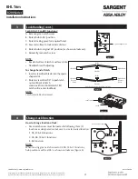
For 04, 06, 13 and 31 Functions:
A. Remove green catch screw.
B. Rotate hub to 45° position.
C. Rotate locking piece for required hand.
D. Face red surface to locked side of door.
E. Rotate hub to original 45° position (as shown on lockcase).
F. Reinstall green catch screw.
NOTE:
• Beveled surface of latch must face strike.
• Deadlatch is self adjusting.
To change hand of latch:
1. insert screwdriver blade into the spade
shaped slot.
2. Rotate screwdriver 90° to push latch
out until back of latch
clears lock front. Rotate latch 180°.
Latch will re-enter lockbody.
NOTE:
Latch cannot be unscrewed.
4
Change Lock Function
How to change function of lock:
• Green catch screw must be located in following
three (3)
locations as designated on lock case to create desired function:
1. 05, 37 & 38 functions
2. 04, 06, 13 & 31 functions
3. 36 function
NOTE:
When moving green catch screw to 04, 06, 13 & 31 functions,
hub position must be at 45° as shown on lockcase (Figure 6).
Spade Shaped Slot
Figure 3
Inside
Inside
Outside
Right Hand
Right Hand
Reverse
Bevel
Left Hand
Left Hand
Reverse
Bevel
Outside
Door Hands Determined From Outside
Figure 4
Latch
Lock Front
Figure 5
Green Catch Screw
Figure 6


