background image

59

ASSA ABLOY Hospitality

66 8003 016-3

Visionline settings

1. Double click on 

Thermostat

profiles

 under the

 Lists

 tab 

in the navigation window. 

2. In the 

Thermostat profiles

 dialog:

click 

Add

 to add a new thermostat

profile, or mark an existing
thermostat profile and click
p

roperties

.  

3. In the 

Thermostat profile details

dialog, choose the 

Misc

 alternative

in the left pane.

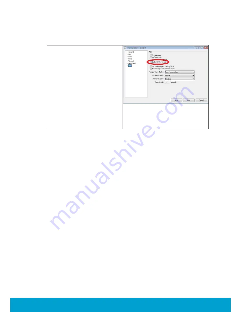
4. Make sure that the checkbox 'Suite

with foyer door' is unmarked. 

5. If it is a new thermostat profile, 

fill in all necessary information
under the different alternatives in
the left pane of the dialog.

6. Click 

Save

 and 

Close

.  

Figure C11


Содержание Orion

Страница 1: ...1 ASSA ABLOY Hospitality 66 8003 016 3 Installation Manual Orion High Voltage Thermostat DRAFT ...

Страница 2: ...on or repair in contravention of this document is at your own risk ASSA ABLOY does not assume any responsibility for incidental or consequential damages arising from the use of this manual All information and drawings in this document are the property of ASSA ABLOY Unauthorized use and reproduction is prohibited VingCard and Elsafe are registered trademarks of ASSA ABLOY ...

Страница 3: ...gh voltage terminal block 8 pole 5 0mm spacing 17 3 1 4 3 Switch output 17 3 1 4 4 Proportional output 18 3 1 4 5 Extra input 19 3 1 4 6 Wired door switch 20 3 1 4 7 Outputs N L RV Y and W 22 3 1 4 8 More about live output 23 3 1 4 9 Fan outputs 23 3 1 4 10 Connection example for floating valve 24 3 2 To install an RF door switch 24 3 2 1 RF door switch dimensions 25 3 2 2 RF door switch magnet di...

Страница 4: ...ings 57 To read out the thermostat status 57 Online network tree 58 To set up a suite with two rooms not foyer 58 VingCard door locks 59 Visionline settings 60 To set up the online network 61 To initialize the master thermostat with suite settings 61 Online network tree 62 Other guest door locks than VingCard 63 To set up the online network 64 To configure the door switches 64 Online network tree ...

Страница 5: ...iguration in offline scenarios 73 To add the lock to the in room network 77 Appendix E To install an external motion sensor 78 Quick reference of technical data 78 Motion sensor dimensions 79 Motion sensor locations 80 Appendix F Read more 80 Revision history ...

Страница 6: ...s been tested and found to comply with the limits for a Class B digital device pursuant to part 15 of the FCC Rules These limits are designed to provide reasonable protection against harmful interference in a residential installation This equipment generates uses and can radiate radio frequency energy and if not installed and used in accordance with the instructions may cause harmful interference ...

Страница 7: ...esser gain approved for the transmitter by Industry Canada To reduce potential radio interference to other users the antenna type and its gain should be so chosen that the equivalent isotropically radiated power e i r p is not more than that necessary for successful communication These radio transmitters IC9514A 683081118C1 and IC9514A TZENHV have been approved by Industry Canada to operate with t...

Страница 8: ...r daily operations when the system is in use see Daily use manual Orion High Voltage Thermostat In that document more information about SysMon System Monitor features is also found For more information about the Orion Service software see Quick reference guide Orion Service A main task for Orion EMS is to determine whether or not a guest room is physically occupied When a room is not occupied Orio...

Страница 9: ...ated to the ordering department 1 Double click on System settings under the Reports tab in the navigation window of Visionline System settings is available even if you are not logged on 2 Communicate your system code to the order department see order acknowledgement for phone number and e mail address The system code can also be entered in the Ordering web page when making the order To install an ...

Страница 10: ...h it is installed Figure 2 The master controller of the in room system is the thermostat shown in Figure 2 To the guest this device appears and operates as a standard digital thermostat however this device also receives entry and exit information from the door lock or switch as well as motion detected information from the motion sensor This information is used to determine the occupancy status of ...

Страница 11: ...e Thermostat details dialog you should also choose the profile to which the thermostat should belong If no applicable thermostat profile exists in Visionline create one according to chapter 4 4 Initialize the thermostat with room number and also with parameters according to the chosen thermostat profile follow the Initialize section in Quick reference guide Orion Service Note If one or more parame...

Страница 12: ...12 ASSA ABLOY Hospitality 66 8003 016 3 3 1 2 Thermostat dimensions Dimensions in mm inches Figure 5 Note This thermostat is an independently mounted control for surface mounting ...

Страница 13: ...ng holes do not fit the installed junction box or if no junction box is installed use a PZD 2 screw driver to mount the wall bracket with the four enclosed 3 5x25 screws 2 Connect to the two terminal blocks according to here Note See a description of the different inputs and outputs in the sections Low voltage terminal block and High voltage terminal block Figure 9 Figure 10 Figure 11 3 Use a PZD ...

Страница 14: ... See details about the low voltage terminal block here and about the high voltage terminal block here For connection examples click the links below Switch output Proportional output Extra input and wired door switch Outputs N L RW Y and W Fan outputs Figure 14 Important The cabling is different for the two terminal blocks due to different sizes of the blocks Low voltage cable maximum cable cross s...

Страница 15: ...s an input for a switch connected between the input and the GND terminal Primary function Used as input from a card switch or a wired motion sensor Alternative function Input for 2 pipe temperature sensor hot cold water this sensor can either be a bimetal switch open or closed depending on the temperature it senses or a 1k NTC resistor connected between this input and the GND terminal The 1k NTC r...

Страница 16: ...ote For information about fan settings in Visionline click here Note For information about live output click here RV Reversing valve Type 1 action Max load 0 5A Primary function Used for switching between summer winter cold hot water in the pipes of a 2 pipe system Alternative functions must be set up in Visionline Mains voltage output when the room is occupied Mains voltage output when the guest ...

Страница 17: ...17 ASSA ABLOY Hospitality 66 8003 016 3 3 1 4 3 Connection examples for switch output Figure 15 3 1 4 4 Connection example for proportional output Figure 16 ...

Страница 18: ...ity 66 8003 016 3 3 1 4 5 Connection examples for extra input Note NO normally open NC normally closed in the below pictures refer to the state of the switch when the card is not inserted or motion is not detected Figure 17 ...

Страница 19: ... ASSA ABLOY Hospitality 66 8003 016 3 3 1 4 6 Connection examples for wired door switch Note NO normally open NC normally closed refers to the state of the switch when the door or window is open Figure 18 ...

Страница 20: ... conditioning can only be used for heating In most cases cold hot water in the pipes is changed twice a year Spring Autumn through an actuator connected to the cool output on the thermostat In a 4 pipe system there are two pipes in and two pipes out one set of pipes in out has cold water and the other set of pipes in out has hot water The thermostat can choose whether cooling or heating is applica...

Страница 21: ...21 ASSA ABLOY Hospitality 66 8003 016 3 Other connection examples for the outputs N L RV Y and W Figure 20 ...

Страница 22: ...ut RV output The thermostat is connected to 110 VAC or 230VAC To be able to disconnect a load one of the connections is broken by one of the two items below relay applicable for Fan 1 Fan 3 tria applicable for W output Y output and RV output Neutral is connected to one of the load connections while Live is connected to the other connection see Figure 21 Figure 21 ...

Страница 23: ...e deactivating the valves close slowly for the desired time Example Figure 23 When the thermostat is in heating mode the W output is used for increasing the temperature and the RV output is used for decreasing the temperature When the thermostat is in cooling mode the Y output is used for decreasing the temperature and the RV output is used for increasing the temperature To control the floating va...

Страница 24: ... AA batteries and the kit also includes a magnet see Figure 25 and two screws The door switch can be mounted as it is or on a wall mounted casing see Figure 26 which is purchased separately Note For best operation the magnet should be installed maximum 10 mm 25 6 from the reed switch which is located as in Figure 24 Note It is also possible to use a wired door switch without radio click here for d...

Страница 25: ...25 ASSA ABLOY Hospitality 66 8003 016 3 3 2 2 RF door switch magnet dimensions Note The magnet must be mounted maximum 10 mm 25 64 from the door switch Figure 25 3 2 3 Wall mounted casing Figure 26 ...

Страница 26: ...arameters of a thermostat profile are at a later occasion updated these new parameters are automatically sent to all concerned online thermostats If the thermostats are not online they must be updated via the Initialize alternative in Orion Service 1 Double click on Thermostat profiles under the Lists tab in the Visionline navigation window 2 Click Add to add a new thermostat profile or mark an ex...

Страница 27: ... input door switch exterior input Normally open normally closed Normally open DSW int input door switch interior input Normally open normally closed Normally open Extra input Not used wired motion sensor pipe temperature sensor Note If Wired motion sensor is chosen it is also possible to make a further choice Delay wired motion sensor This can be applicable in warm countries where there is a great...

Страница 28: ...lable If the pipe temperature sensor is a bimetal switch open or closed depending on the temperature it senses choose for Pipe temperature sensor whether it should be Cooling or Heating If the pipe temperature sensor is an 1k NTC resistor a Trigger level in the range 0 100 for switching between heat and cool should be chosen When the temperature reaches the switch over temperature default 3 ºF thi...

Страница 29: ... the output if all default values are used The range for the regular output value is 0 10V Integral gain reset The Integral gain reset describes to the HVAC system regulator what gain it can use when integrating the previous average temperature values in order to settle the temperature around the desired set value Derivative time The Derivative time describes to the HVAC system regulator what gain...

Страница 30: ...ve Max runtime There are three different values for runtime i e how long the floating valve should operate related to the difference between measured temperature and setpoint Max runtime Medium runtime and Min runtime Based on a calculation of the selected deadband and the temperature deviation from setpoint the thermostat chooses an applicable valve throttle Example 1 If the temperature differenc...

Страница 31: ...lable If the pipe temperature sensor is a bimetal switch open or closed depending on the temperature it senses choose for Pipe temperature sensor whether it should be Cooling or Heating If the pipe temperature sensor is an 1k NTC resistor a Trigger level in the range 0 100 for switching between heat and cool should be chosen When the temperature reaches the switch over temperature default 3 ºF thi...

Страница 32: ... the output if all default values are used The range for the regular output value is 0 10V Integral gain reset The Integral gain reset describes to the HVAC system regulator what gain it can use when integrating the previous average temperature values in order to settle the temperature around the desired set value Derivative time The Derivative time describes to the HVAC system regulator what gain...

Страница 33: ...ve Max runtime There are three different values for runtime i e how long the floating valve should operate related to the difference between measured temperature and setpoint Max runtime Medium runtime and Min runtime Based on a calculation of the selected deadband and the temperature deviation from setpoint the thermostat chooses an applicable valve throttle Example 1 If the temperature differenc...

Страница 34: ...sumption for the three cases Cooling Heating and Fan only can be entered at Estimated consumtion first expand HVAC in the left pane of the Thermostat profile details dialog and choose Consumption Figure 37 4 3 Fan Figure 38 1 At Control choose whether the control should be manual default auto this choice will disable the fan button of the thermostat ...

Страница 35: ... for guest comfort reasons not change Note The Fan on when satisfied function will only apply to an occupied room 5 At Cool down duration Fan time and Fan speed of the fan during cool down period can be chosen It can also be chosen whether cool down should apply only when in cool or only when in heat mark the applicable checkbox Fan time default is 2 minutes can be in the range 1 10 minutes Fan sp...

Страница 36: ...ault is 4 F offset and Lower limit default is 4 F offset for setback if a room is unoccupied Figure 40 1 At Unsold setback enter the applicable number of degrees as Upper limit default is 84 F and Lower limit default is 64 F for setback if a room is unsold Figure 41 1 At Occupied limits it is possible to limit the allowed temperature range when the room is occupied If this is the case mark the che...

Страница 37: ...t Room not sold enter the applicable number of hours default is 16 after which an unoccupied room should enter the unsold mode Note If the PMS system sends a check out command the Room not sold parameter will be overridden and timeout will immediately take place Figure 43 4 6 Deadband 1 At Thermostat enter the applicable number of degrees default is 2 F 2 At Heat cool enter the applicable number o...

Страница 38: ... a period of 2 minutes to re circulate the air in the room only for cooling mode Figure 46 3 Dwell off time should normally be unmarked see details here Figure 47 4 If the checkbox Guest door is exterior is marked default is unmarked the door to the room will be treated as an exterior door If the door is opened the HVAC will turn off either when the door has been open for 20 seconds short timeout ...

Страница 39: ...dity control is chosen default is unmarked the thermostat will implement control measures if the humidity in the room gets too high Note The control measures will only be implemented when the room is unoccupied or unsold Figure 50 7 If the checkbox On exterior open keep lights on is marked default is unmarked the lights will be left on if the exterior door timeout has been triggered by the wired i...

Страница 40: ...pre condition time is marked which is default the lights are enabled according to the chosen intelligent switch setting during the pre condition time Note This parameter requires that the Online option has been set in Visionline Figure 53 10 If the checkbox Set door state to closed when door ajar alarm received is marked default is unmarked the door state is set to closed once the door ajar timeou...

Страница 41: ...pancy status If intelligent switch is applicable normally Use RV output should be marked unless the air handler is a heat pump In the latter case mark Use G2 output instead Figure 56 13 If desired it is possible to have a Welcome scene which is activated when the occupancy state for a room changes from unsold to unoccupied The available alternatives for welcome scene are default is disabled disabl...

Страница 42: ... expires the unoccupied setback will be assumed The pre condition time can be 1 12 hours or disabled default is 2 hours Note This parameter requires that the Online option has been set in Visionline Figure 59 16 Default set point is the temperature which the thermostat is set to until a guest changes the temperature The thermostat will also return to the Default set point after check out Figure 60...

Страница 43: ...ock and motion sensor will be joined to this thermostat When the steps in sections 5 1 and 5 2 have been performed the in room network is operational Note To use the Orion Service software connections to the application server must be made according to Quick reference guide Orion Service 5 1 To join the thermostat to the network 1 To be able to join the thermostat to the gateway or router it is fi...

Страница 44: ...k the Discovery button see Figure 62 The thermostat will connect to the open gateway router 6 To see if the thermostat was able to join the network click the Check status button in the Configure Device section of Orion Service If the joining was successful the message Device is online is shown 7 With the thermostat joined to its gateway router right click on the gateway router in SysMon and select...

Страница 45: ... is shown If that message is not displayed wait a few more seconds and check the status again If still offline repeat the discovery process Figure 65 7 The lock is joined to the thermostat by using a Discovery card Depending on lock model there will be a green flash and or a chirp indicating that the lock has been set into discovery mode Wait a few seconds and then present the Check Status card at...

Страница 46: ... Service Click the Forbid Join button see Figure 66 Failure to perform this step will result in problems when setting up the network in nearby rooms 11 Right click on the thermostat in the Online network tree in SysMon and choose Get user description Make sure that the description says no at Join permitted Figure 66 See User manual Online option for information about issuing these cards ...

Страница 47: ...tart button in Orion Service Item Status shown Door switch Yes No Motion sensor Yes No HVAC Fan speed Occupancy Unsold unoccupied occupied unknown Temp sensed set Temp sensed is the temperature in the room temp set is the temperature which the guest has set on the thermostat Door state Opened closed Ext door state Opened closed for an external door applicable if a door switch has been configured a...

Страница 48: ...t the door and motion events are logged as shown in the example in Figure 68 Figure 68 5 Run a status check by selecting the Status section in the left part of the Orion Service software window making sure that the service cable is plugged into plugged into the thermostat and clicking the Readout button Make sure that the motion sensor lock and thermostat all say Offline No see Figure 69 Figure 69...

Страница 49: ...tected Ensure that the range is sufficient to pick up motion in the room The LED will be active for 10 minutes and then automatically turn off The system is now ready for use 12 Test the range of the motion sensor First make sure that the door is open as this will ensure that the motion sensor is not deactivated by the thermostat Choose the Configure device section in the left part of the Orion Se...

Страница 50: ... Temperature display range 2 digit display Adjustable setpoint temperature range 17 C 32 C 62 F 90 F Environment Normal indoor environment Pollution degree 2 Operating temperature range 0 C 55 C 32 F 130 F Service device Orion Service software and service cable RJ12 to 3 5mm stereo jack Radio RF signals ZigBee 2006 Lock to thermostat Door open staff card Door open guest card Door open from inside ...

Страница 51: ...t pump is chosen as HVAC type In the heat pump case the thermostat will automatically force the dwell off time to be on it is then 5 minutes and cannot be changed The dwell off time prevents short cycling of the compressor Required Visionline version 1 15 0 or higher Required Orion Service version 1 3 0 or higher for full functionality Table A1 ...

Страница 52: ...e to Orion Service Note Upgrading the endnode firmware in the thermostat may take several minutes Note If the firmware in thermostat controller and thermostat should be upgraded at the same time it is recommended to start upgrading the thermostat controller first 1 Check under Upload firmware in Orion Service what firmware that is included there if no later firmware exists follow the steps under U...

Страница 53: ...ick OK Figure B4 7 In the Orion Service software choose Download firmware Click Query to list the available module firmware versions on the Visionline server 8 Mark the applicable firmware version and click Download 9 If applicable repeat step 7 with other firmware that is to be uploaded 10 Plug the service cable into the thermostat or motion sensor depending on which module that is to be upgraded...

Страница 54: ... guest door leading to a suite of rooms two or more rooms see details here To set up a suite with foyer door One possible suite configuration is to have a foyer door and behind the foyer door two rooms which form a suite In the example shown in Figure C1 the suite contains the rooms 102 and 103 each room has one thermostat and one motion sensor Room 102 is the master room of the suite and hence th...

Страница 55: ...PAN personal area network To set up the network follow the steps below 1 Double click on SysMon exe in the Visionline installation folder to open SysMon System Monitor which is used for managing the online network 2 Log on to SysMon go to File Log on and enter user ID and password At Operator card choose the applicable card encoder and click Enter 3 Go to View Online Network to show the Online Net...

Страница 56: ...he applicable door area in this example Floor 1 and mark the master room in this example 102 Figure C4 4 At Suite settings Enter the Suite room slave room in this example it is 103 Leave the Share occupancy checkbox empty this is only applicable when there is just one door to the entire suite click here for more information about that configuration Figure C5 5 Click the Initialize button Note It i...

Страница 57: ...etwork tree in SysMon will typically look as in the example in Figure C9 1 The thermostats have been initialized with regular parameters i e all parameters except for those related to suite 2 Thermostats motion sensors and guest room locks have been connected to the online network according to chapter 5 3 The foyer lock has been connected to the master room thermostat according to chapter 5 4 The ...

Страница 58: ...nlocked with a key by staff or by the guest with access to both rooms The Orion system must be connected to a server via a gateway in order for the thermostats in the two rooms to be able to communicate The link between the two rooms is configured via Orion Service The suite activation will be automatic if the requirements mentioned in the sections VingCard guest door locks and Other guest door lo...

Страница 59: ...ew thermostat profile or mark an existing thermostat profile and click properties 3 In the Thermostat profile details dialog choose the Misc alternative in the left pane 4 Make sure that the checkbox Suite with foyer door is unmarked 5 If it is a new thermostat profile fill in all necessary information under the different alternatives in the left pane of the dialog 6 Click Save and Close Figure C1...

Страница 60: ...e 4 Install the gateway see User manual Online option for details 5 Initialize thermostat 102 with normal parameters i e all parameters except for those related to suite To do this use the Initialize alternative in Orion Service but leave the Suite settings empty See Daily use manual Orion EMS for details about Initialize 6 Connect thermostat 102 to the gateway see chapter 5 for details 7 Connect ...

Страница 61: ...or more information about that configuration Figure C14 5 Click the Initialize button Note It is only the master room that is initialized with suite settings so steps 1 4 above are never performed for the slave room Figure C15 Online network tree When steps 1 4 below have been performed the Online Network tree in SysMon will typically look as in the example in Figure C16 1 The thermostats have bee...

Страница 62: ...ting door between the two rooms there should be three door switches set up under the master room one door switch at the guest door and two door switches at the connecting door When the master thermostat reads both door switches as open it will activate the suite by sending a message to the slave thermostat thermostat 103 in Figure C17 and share events from that point If one or both of the connecti...

Страница 63: ...se the Initialize alternative in Orion Service but leave the Suite settings empty See Daily use manual Orion EMS for details about Initialize 6 Connect thermostat 102 to the gateway see chapter 5 for details 7 Connect motion sensor 102 to thermostat 102 see chapter 5 for details 8 Connect door switch guest 102 door switch at the guest door in room 102 to thermostat 102 see chapter 5 for details 9 ...

Страница 64: ...he connecting door in room 103 Example of suite status for master room thermostat Figure C19 Online network tree When steps 1 4 below have been performed the Online Network tree in SysMon will typically look as in the example in Figure C20 1 The thermostats have been initialized with regular parameters i e all parameters except for those related to suite 2 Thermostats motion sensors and door switc...

Страница 65: ...tains the rooms 1021 1022 and 1023 each room has one thermostat and one motion sensor Room 1021 is the master room for room 1022 and room 1022 is the master room for room 1023 The lock 102 is connected to the thermostat in the first room i e to thermostat 1021 when the online network is set up Note For more information about the suite functionality see section More about how the suite works Figure...

Страница 66: ...details 5 Initialize thermostat 1021 with regular parameters i e all parameters except for those related to suite To do this use the Initialize alternative in Orion Service but leave the Suite settings empty See Daily use manual Orion EMS for details about Initialize 6 Connect thermostat 1021 to the gateway see chapter 5 for details 7 Connect motion sensor 1021 to thermostat 1021 see chapter 5 for...

Страница 67: ...re C21 i e three rooms in a chain To initialize the thermostat in the first room of the suite 1 Choose Initialize in the left pane of the Orion Service window 2 Click the plus sign for the applicable door area in this example Floor 1 and mark the master room in this example 1021 Figure C24 3 At Suite settings Enter the Suite room slave room in this example 1022 Mark the Share occupancy checkbox Fi...

Страница 68: ...the applicable door area in this example Floor 1 and mark the master room in this example 1022 Figure C27 3 At Suite settings Enter the Suite room slave room in this example 1023 Mark the Share occupancy checkbox Figure C28 4 Click the Initialize button Note It is only the master room that is initialized with suite settings so steps 1 3 above are never performed for the slave room Figure C29 ...

Страница 69: ...ve been performed the online network tree in SysMon will typically look as in the example in Figure C32 1 The thermostats have been initialized with regular parameters i e all parameters except for those related to suite 2 Thermostats motion sensors and the lock have been connected to the online network according to chapter 5 3 All thermostats except for the last one in the chain see Figure C23 fo...

Страница 70: ...l get a suite card which gives access to both rooms in the suite the foyer door which should be closed when the guest arrives Figure C33 When the guest uses the suite card in the foyer door the door will send information to the thermostat in the master room i e in this example 102 that a suite card has been used in the foyer door and the thermostats should now share the state occupied or unoccupie...

Страница 71: ... a single room and not as part of a suite the card is valid in the room to a certain date and time Note The thermostats in rooms 102 and 103 will now only consider the door events for their own room and will not share the occupancy state with the thermostat in the other room Suite with one door only For the suite configuration described in this section i e with only one guest door leading to two o...

Страница 72: ...er firmware Figure D1 The RFID lock in the configuration pictures above must be prepared in two ways it must be online with the in room network EMI events must be enabled in the lock This can be done either with an Enable EMI events card or via Lock Service see the applicable one of sections Enabling EMI events via card and Enabling EMI events via Lock Service Note The EMI events will be sent to t...

Страница 73: ...reason forgotten it will automatically be executed 15 minutes after the Permit join command was executed Set channels Default is that all channels are ON the 1 indicates ON the best channel will automatically be chosen so normally the Set channels command is not needed Get network This configuration shows the in room network Note When hovering with the cursor over an item in the network the toolti...

Страница 74: ... in the picture example 26 and click the Set channels button 8 Mark the thermostat and click the Permit join button Figure D4 9 Right click on the thermostat and choose Get user description Information about the thermostat will be shown see picture to the right Make sure that the channel is correct it says yes at Join permitted Note If it does not say yes at Join permitted click the Permit join bu...

Страница 75: ...tted Figure D8 16 Issue a Discovery card in Visionline Go to Start Programs VisiOnline VisiOnline and log on Double click on ZigBee configuration under the Cards tab in the navigation window Browse to choose a Card holder and enter No of days At Type choose Start discovery in ZigBee If applicable tick the checkbox Print receipt Click Make card and present a card at the encoder 17 Present the Disco...

Страница 76: ...ign in front of the thermostat the lock will appear in the network tree 20 Mark the thermostat and click the Forbid join button 21 Right click on the thermostat and choose Get user description Make sure that the description says no at Join permitted Figure D11 ...

Страница 77: ... this section The motion sensor is used to detect motion in the room and send this information via the ZigBee endnode to the to the room controller thermostat The device is designed to be ceiling or wall mounted and is powered by 3AA batteries No physical connections are required thus making the installation simple Figure E1 The motion sensor is a battery operated device that may be installed on t...

Страница 78: ...ries 4 5 VDC Mounting Ceiling or wall surface mounting Keyhole type for easy installation and battery relpacement access Range 360 degrees 8 meters horizontal 3 meters vertical Messages transmitted Motion detected Battery status Diagnostics Integrated LED only enabled for diagnostics Table E1 Motion sensor dimensions in mm inches Figure E3 ...

Страница 79: ...sible and give as much coverage to the room as possible Figure E4 shows the range of the motion sensor when placed on the ceiling This range is somewhat reduced when installed on the wall The range shown is a general guideline and the sensor is designed to cover an area of about 8m 26 feet in diameter To check the location it is advisable to activate the motion LED using the service device and tes...

Страница 80: ...t commissioning when thermostat controller is used has been added KG October 20 2011 Section about Recommended wire specification modified due to requirements for UL certification Picture in section Line to low voltage conversion exchanged due to requirements for UL certification KG February 16 2012 Added reference to Upgrading an RFID lock for an Orion EMS offline scenario for information about w...

Страница 81: ...KG September 13 2012 Clarified about V in section 3 3 Clarified about V and signal inputs in section 4 1 Added section 4 1 1 about RS 485 interface Removed information about USB Xpress in Appendix A KG March 7 2014 Added information about suites KG February 19 2016 Layout updated Added cool down parameter KG October 12 2016 Modified maximum value of room not occupied timer to 120 minutes KG ...

Страница 82: ...05 7670 ASSA ABLOY Hospitality EMEA ASSA ABLOY Hospitality North America Phone 47 69 24 50 00 E mail emea hospitality assaabloy com E mail lam hospitality assaabloy com Phone 1 972 907 2273 ASSA ABLOY Hospitality Latin America E mail northam hospitality assaabloy com Phone 52 55 36 40 12 00 www assaabloyhospitality com ...

Отзывы: