5
Patent pending and/or patent www.assaabloydss.com/patents
Medeco is a brand associated with ASSA ABLOY High Security Group, Inc., an ASSA ABLOY Group company. Copyright © 2020. ASSA ABLOY High Security Group, Inc.
All rights reserved. Reproduction in whole or in part without the express written permission of ASSA ABLOY High Security Group, Inc. is prohibited.
XT Identification and Programming Device (IPD)
Mounting and Installation
Step 2
With the power and network cables passing through the center hole, install the rear
Mounting Bracket. See the available mounting configurations above (1A – 1D).
Step 3
Connect the power cord and the network cable to the ports located on the internal circuit
board. Secure the network and power cord through the provided zip tie loops to relieve
the pressure on the connectors. See the image below for the correct routing of the
cables.
Warning: The Importance of Proper Cable Routing and Using the Wire Ties
Step 4
Place the outer IPD assembly over the Mounting Bracket. During this process, ensure
that all cables and wires are clear. Continue to insert the Outer Assembly over the
Mounting Bracket until the enclosure holes (2 each side) are in alignment. Insert the
tamper proof screws using the provided driver, 4 places.
Step 5
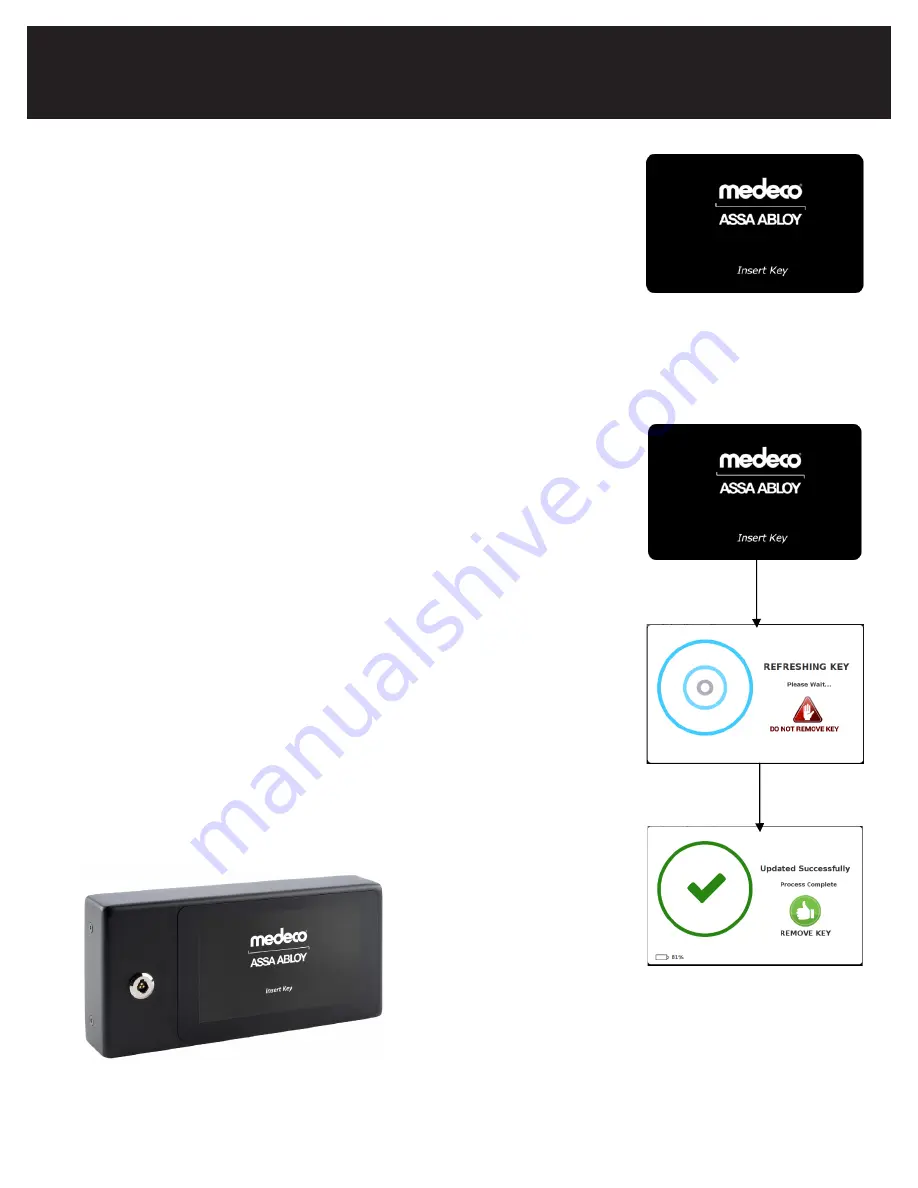
With the IPD installed and the cables connected, the IPD will automatically connect to the
XT Web Manager and display a screen with the Medeco splash screen, prompting the user
to Insert Key at the bottom of the screen. If the IPD does not change from the Pairing
screen after 2-5 minutes, refer to the troubleshooting section in the XT Web Manager
User Guide for the XT IPD.
(1)
TO PREVENT DAMAGE - The wires ties are necessary to relieve strain on the network and power connections. Please handle these
cables cautiously until the wire ties are securing the cables from movement at these connections.
Step 4
Place the outer IPD assembly over the Mounting Bracket. During this process,
ensure that all cables and wires are clear. Continue to insert the Outer Assem-
bly over the Mounting Bracket until the enclosure holes (2 each side) are in
alignment. Insert the tamper proof screws using the provided driver, 4 places.
Step 5
With the IPD installed and the cables connected, the IPD will automatically
connect to the XT Web Manager and display a screen with the Medeco splash
screen, prompting the user to Insert Key at the bottom of the screen. If the IPD
does not change from the Pairing screen after 2-5 minutes, refer to the trou-
bleshooting section in the XT Web Manager User Guide for the XT IPD.
Test Your Setup
Step 6
To test the installation, insert the XT key with a pending or active schedule into
the programming port to verify the IPD operation.
TEST YOUR SETUP
Step 6
To test the installation, insert the XT key with a pending or active schedule into the
programming port to verify the IPD operation.
You have now successfully installed and tested you XT Identification and Programming
Device (IPD).
You have now successfully installed and tested you XT Identification and
Programming Device (IPD).
TEST YOUR SETUP
Step 6
To test the installation, insert the XT key with a pending or active schedule into the
programming port to verify the IPD operation.
You have now successfully installed and tested you XT Identification and Programming
Device (IPD).
XT Identification and Programming Device (IPD)
Mounting and Installation
Содержание medeco XT IPD
Страница 1: ...IPD Installation and Programming Guide ...


