background image

4

Patent pending and/or patent www.assaabloydss.com/patents

Medeco is a brand associated with ASSA ABLOY High Security Group, Inc., an ASSA ABLOY Group company. Copyright © 2020. ASSA ABLOY High Security Group, Inc. 

All rights reserved.  Reproduction in whole or in part without the express written permission of ASSA ABLOY High Security Group, Inc. is prohibited.

Step 1 

Remove the rear Mounting Bracket of the IPD and run the network and power cables through the square hole in the center 

of the rear plate.

Note: Option Power and Network Cable Access

Step 2

With the power and network cables passing through the center hole, install the rear Mounting Bracket.  See the available 

mounting configurations above (1A – 1D).

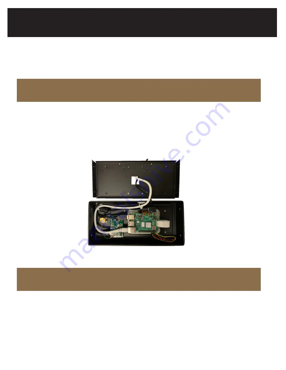
Step 3  

Connect the power cord and the network cable to the ports located on the internal circuit board. Secure the network and 

power cord through the provided zip tie loops to relieve the pressure on the connectors.  See the image below for the 

correct routing of the cables.

(1)  Two knockout holes are located along the bottom surface of the XT IPD enclosure.  These knockouts can be re-

moved for optional access of the power and network cables.  After the cables are placed through the holes, insert 

the provided bushings to protect the cables from the damage due to rubbing against the edges of the holes.


Step 2 

With the power and network cables passing through the center hole, install the rear 

Mounting Bracket.  See the available mounting configurations above (1A – 1D). 


Step 3   

Connect the power cord and the network cable to the ports located on the internal circuit 

board. Secure the network and power cord through the provided zip tie loops to relieve 

the pressure on the connectors.  See the image below for the correct routing of the 

cables. 


 Warning: The Importance of Proper Cable Routing and Using the Wire Ties 


Step 4 

Place the outer IPD assembly over the Mounting Bracket.  During this process, ensure 

that all cables and wires are clear. Continue to insert the Outer Assembly over the 

Mounting Bracket until the enclosure holes (2 each side) are in alignment.  Insert the 

tamper proof screws using the provided driver, 4 places. 


Step 5  

With the IPD installed and the cables connected, the IPD will automatically connect to the 

XT Web Manager and display a screen with the Medeco splash screen, prompting the user 

to Insert Key at the bottom of the screen. If the IPD does not change from the Pairing 

screen after 2-5 minutes, refer to the troubleshooting section in the XT Web Manager 

User Guide for the XT IPD.  


(1)


TO PREVENT DAMAGE - The wires ties are necessary to relieve strain on the network and power connections.  Please handle these 
cables cautiously until the wire ties are securing the cables from movement at these connections. 

Warning: The Importance of Proper Cable Routing and Using the Wire Ties

(1)  TO PREVENT DAMAGE - The wires ties are necessary to relieve strain on the network and power connections.  

Please handle these cables cautiously until the wire ties are securing the cables from movement at these 

connections.

XT Identification and Programming Device (IPD)

Mounting and Installation

Содержание medeco XT IPD

Страница 1: ...IPD Installation and Programming Guide ...

Страница 2: ...pany Copyright 2020 ASSA ABLOY High Security Group Inc All rights reserved Reproduction in whole or in part without the express written permission of ASSA ABLOY High Security Group Inc is prohibited The XT IPD Can Be Mounted In A Variety Of Configurations XT Identification and Programming Device IPD Mounting and Installation 2 XT IPD Pairing with the XT Web Manager 6 Operation of the XT IPD 7 Trou...

Страница 3: ...oftware and browsing to the section on the XT Identification and Programming Device Update Configuration Settings 2 If the IPD is being installed in a customer hosted solution the URL should be changed to the URL of your XT Web Manager Application Server as described in the XT Web Manager User Guide 1 Two knockout holes are located along the bottom surface of the XT IPD enclosure These knockouts c...

Страница 4: ...gurations above 1A 1D Step 3 Connect the power cord and the network cable to the ports located on the internal circuit board Secure the network and power cord through the provided zip tie loops to relieve the pressure on the connectors See the image below for the correct routing of the cables Warning The Importance of Proper Cable Routing and Using the Wire Ties Step 4 Place the outer IPD assembly...

Страница 5: ...mper proof screws using the provided driver 4 places Step 5 With the IPD installed and the cables connected the IPD will automatically connect to the XT Web Manager and display a screen with the Medeco splash screen prompting the user to Insert Key at the bottom of the screen If the IPD does not change from the Pairing screen after 2 5 minutes refer to the trou bleshooting section in the XT Web Ma...

Страница 6: ...character pairing code If the IPD will be installed in a self hosted solution you should change the URL prior to moving on to step 4 You can find more info on this procedure in the Update Configuration Settings section Step 2 Within the XT Web application navigate to the Administration XT Programmers page and select Pair New Device and enter the pairing code displayed on the IPD as well as a short...

Страница 7: ...ation enter your PIN in order to service your Key Once the IPD has been successfully setup you can Service Medeco XT keys G2 G3B G3S Update configuration settings Servicing Medeco XT Keys Insert XT Key Insert the XT Key and rotate counter clockwise to lock it into position Enter PIN if enabled If required by your Organization enter your PIN in order to service your Key Progress of Service is Displ...

Страница 8: ...cable will display toward the bottom of the screen Remove the Key Error Updating Try removing and re inserting the key after the Insert Key screen re appears Verify with Admin that there are no problems with your schedule Ensure your key remains still during the programming process Results Displayed Successful o Battery Level will display in bottom left corner Only available with G3B G3S generatio...

Страница 9: ...m right of the screen Update Configuration Settings If you wish to direct your IPD to a different URL for applications where XT Web is hosted locally you can do this by following one of the three methods listed below Initial Pairing Admin Key Service Server Unavailable Screen Initial Pairing Prior to pairing the Pairing screen will display a small settings icon at the bottom right of the screen On...

Страница 10: ...green check mark circle at in the top right of the screen Admin User Level Restricted Key Service Servicing an Admin User Level key and selecting the setting icon that will display in the bottom right corner of the screen after a successful key service Once selected you will be able to update the URL by entering in the full URL path and selecting the green check mark circle at in the top right of ...

Страница 11: ...ress written permission of ASSA ABLOY High Security Group Inc is prohibited Operation of the XT IPD Once you successfully enter the pairing code you will be able to update the URL by entering in the full URL path and selecting the green check mark circle at in the top right of the screen Once you successfully enter the pairing code you will be able to update the URL by entering in the full URL pat...

Страница 12: ...ecently disconnected from XT Web or is having trouble connecting Disconnected The IPD is no longer connected to XT Web When troubleshooting there are two scenarios where you could encounter problems Prior to Pairing Post Successful Pairing Prior to Pairing If you have entered in the pairing details into XT Web Manager and are unable to pair your IPD you need to verify The Pairing code is entered c...

Страница 13: ... the following details Verify that the network cable is securely connected to the IPD unit as well as the networking device Verify no changes have been made to the network that may block the IPD from connecting to XT Web Manager If the Pairing Status shows Paired on the XT Programmers table and the Connection Status shows Disconnected this indicates that at one point the IPD has been paired succes...

Страница 14: ...mer Service 1 888 633 3264 2020 014 Patent pending and or patent www assaabloydss com patents Medeco is a brand associated with ASSA ABLOY High Security Group Inc an ASSA ABLOY Group company Copyright 2020 ASSA ABLOY High Security Group Inc All rights reserved Reproduction in whole or in part without the express written permission of ASSA ABLOY High Security Group Inc is prohibited ...

Отзывы: