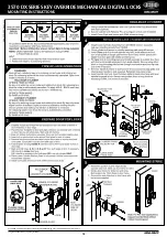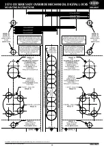
The global leader in door opening solutions
ASSA ABLOY Australia Limited, 235 Huntingdale Rd, Oakleigh, VIC 3166 ABN 90 086 451 907 ©2012
20
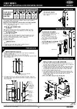
3580 SERIES
MECHANICAL DIGITAL LOCKS FOR METAL DOORS
3580-621
SN500 1296
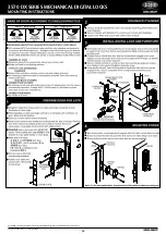
All Lockwood 3580 Series Mechanical Digital Locks are to be mounted in
accordance with these instructions.
Important : Before drilling door ensure correct hand is being installed.
NOTE: CASE DOES NOT need to be Opened, to change HAND
or FUNCTION of LOCK.
TYPE OF LOCK OPERATIONS
STANDARD
Opened from outside by entering correct code and rotating turn knob.
On releasing turnknob the code is automatically cancelled. Open from
inside by handle at all times.
HOLD BACK CYLINDER
OPENED FROM OUTSIDE :
By entering correct code and rotating turn knob. On releasing turn knob
the code is automatically cancelled. To apply HOLD - BACK insert key
into interior cylinder and rotate one full turn, withdraw key.
OPENED FROM INSIDE :
By handle at all times.
HAND OF LOCK
BOLT
1. Determine hand of lock required from hand of door chart.
2. Rotate bolt head to suit latching direction.
HAND OF DOOR
ACCORDING
TO ENGLISH
PRACTICE
RIGHT - HAND DOOR
LEFT - HAND DOOR
OUTSIDE
DOOR OPENING
IN
OUTSIDE
DOOR OPENING
OUT
OUTSIDE
DOOR OPENING
OUT
OUTSIDE
DOOR OPENING
IN
3580 SERIES
MECHANICAL DIGITAL LOCKS
FOR METAL DOORS
LOCK UP WITH LOCKWOOD
TM
1
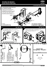
PREPARE LOCK
3. Place template in opening and drill 2 holes 4.5mm diameter and countersink
8.5mm diameter x 90°.
4. Drill appropiate holes to suit lockset to be fitted. Dimensions shown suit
all functions. Note 23mm standard backset shown, others include 25.4mm,
30mm and 38mm.
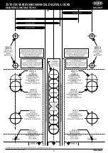
167
R3
156
4.5mm DIA & COUNTERSINK
8.5mm DIA x 90°
25.4
159
69
90
37
BACKSET
27.5
10mm Dia
Mark & Drill
from BOTH sides
14
For HOLDBACK
CYLINDERS ONLY
2 Holes 20mm Dia
Mark & Drill
from INSIDE door
face only
22.5mm Dia
Mark & Drill
from OUTSIDE door
face only
22.5mm Dia
Mark & Drill
from INSIDE door
face only
10mm Dia
Mark & Drill
from BOTH sides
23
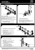
PREPARE DOOR FOR LOCK
1. Establish height that lockset will be on door and mark centreline of door
2. Cut cover plate window 156mm x 25.4mm with 3mm radii.
thickness on door edge.
2
3
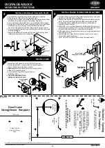
INSTALLING COVER PLATE
4
INSTALL DIGITAL LOCK
FIT LOCK TO DOOR
1. Insert lock into door and secure
with 2 screws.
LOCKS WITHOUT CYLINDER
1. Install Cover Plate and secure
with 2 screws.
HOLD BACK CYLINDER
1. Using a small flat screwdriver, lever out
Cylinder Hole Plug where fitted
and insert cylinder.
2. Secure cylinder with Retainer Pin,
ensuring pin is flush with frontplate.
3. Install Cover plate and secure with
2 screws.
HOLD-BACK
CYLINDER
COVER PLATE
LOCK
CYLINDER
RETAINER
PIN
INSTALL DIGITAL LOCK AND FURNITURE
1. Insert blade end of turn knob spindle into turn knob adaptor and cut
turn knob spindle to length (19mm from Door Face). Insert spindle into
digital lock drive gear with blade end facing out.
2. Fit digital lock to outside door face, with turn knob spindle engaged in
turn knob adaptor. Secure using either short or long mounting plate
screw through cup washer and into top hole. Cut screw if required.
3. Rotate Furniture handle to desired hand.
4. Insert spindle into lock. Insert furniture plate to inside door face with
lever spindle engaged in hub. Secure using furniture mounting screws.
Bottom furniture screw to be located through mortice and into
Furniture Mounting Nut.
NOTE : All SCREWS to be cut flush with door face.
DIGITAL
LOCK
19mm
TURN KNOB
SPINDLE
CUP WASHER
MOUNTING PLATE
SCREW
FURNITURE
PLATE
SPINDLE
FURNITURE
MOUNTING NUT
IMPORTANT :
Attach spindle spring to rear
of spindle before assembling.
FITTING LOCK
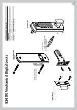
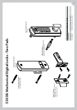
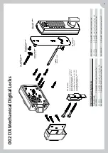
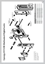
Содержание Lockwood 002 DX
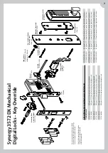
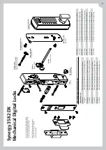
Страница 5: ...DX Mechanical Digital Locks ...
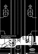
Страница 12: ...Mounting Instructions and Templates ...
Страница 22: ...Notes FOR INFORMATION CALL 1300 LOCK UP 1300 562 587 OR VISIT LOCKWEB COM AU ...
Страница 23: ......

