The global leader in door opening solutions
ASSA ABLOY Australia Limited, 235 Huntingdale Rd, Oakleigh, VIC 3166 ABN 90 086 451 907 ©2012
15
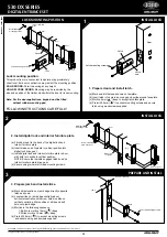
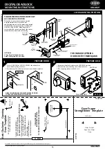
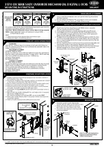
DIGITAL DEADLOCK
MOUNTING INSTRUCTIONS
Door Frame
Strengthener
Strike
JAMB
Door Frame
Strengthener Template
1. Position strike on jamb directly opposite the lock case and mark
outline of strike flange on jamb edge.
2. Mortice area for flange. Depth of flange mortice determines gap.
Note : 3mm maximum gap between lock and installed strike.
3. Position door frame strengthener template in strike flange
mortice as shown below.
4. WARNING: Care must be taken when drilling and affixing screws
to jamb. Screws must NOT come in contact with electrical wires
in jamb. Mark and drill holes as specified on template.
5. Install door frame strengthener and secure using two door frame
strengthener screws.
6. Locate strike over door frame strengthener and secure using
three strike mounting screws.
Note : Pre-drill 3mm Dia x 25mm deep for woodscrews.
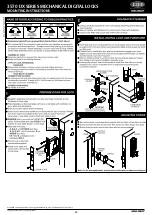
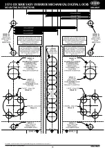
Clockwise
Opening
Door
Template
1. Select CL
OCKWISE or
ANT
I-CL
OCKWISE template
to suit door opening direction.
2. Place template on inside door
face at required height from
floor with
LINE A
positioned
on door edge.
3. Mark and drill holes as
specified on template.
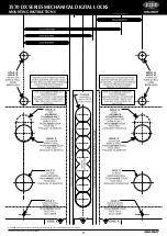
Door Frame
Strengthener Template
DRILL 2 HOLES
5mm Dia x 63mm
Deep
TEAR OFF
FOLD LINE
TEAR OFF
DRILL 4 HOLES
3mm
Dia x 25mm
Deep
DRILL
32mm
Dia HOLE
DRILL HOLE FROM
BOT
H SIDES OF
DOOR.
TO
PREVENT SPLINTERING OF
DOOR F
ACE
THIS W
AY
UP
INSIDE
60mm B
ACKSET
LINE A
USE OT
HER SIDE OF TEMPLA
TE
FOR ANT
I-CL
OCKWISE DOOR
DRILL HOLE
10mm
3mm Max.
5
INSTALL FRAME STRENGTHENER & STRIKE
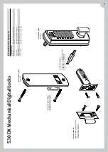
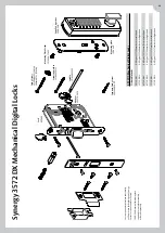
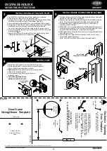
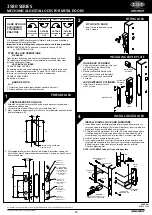
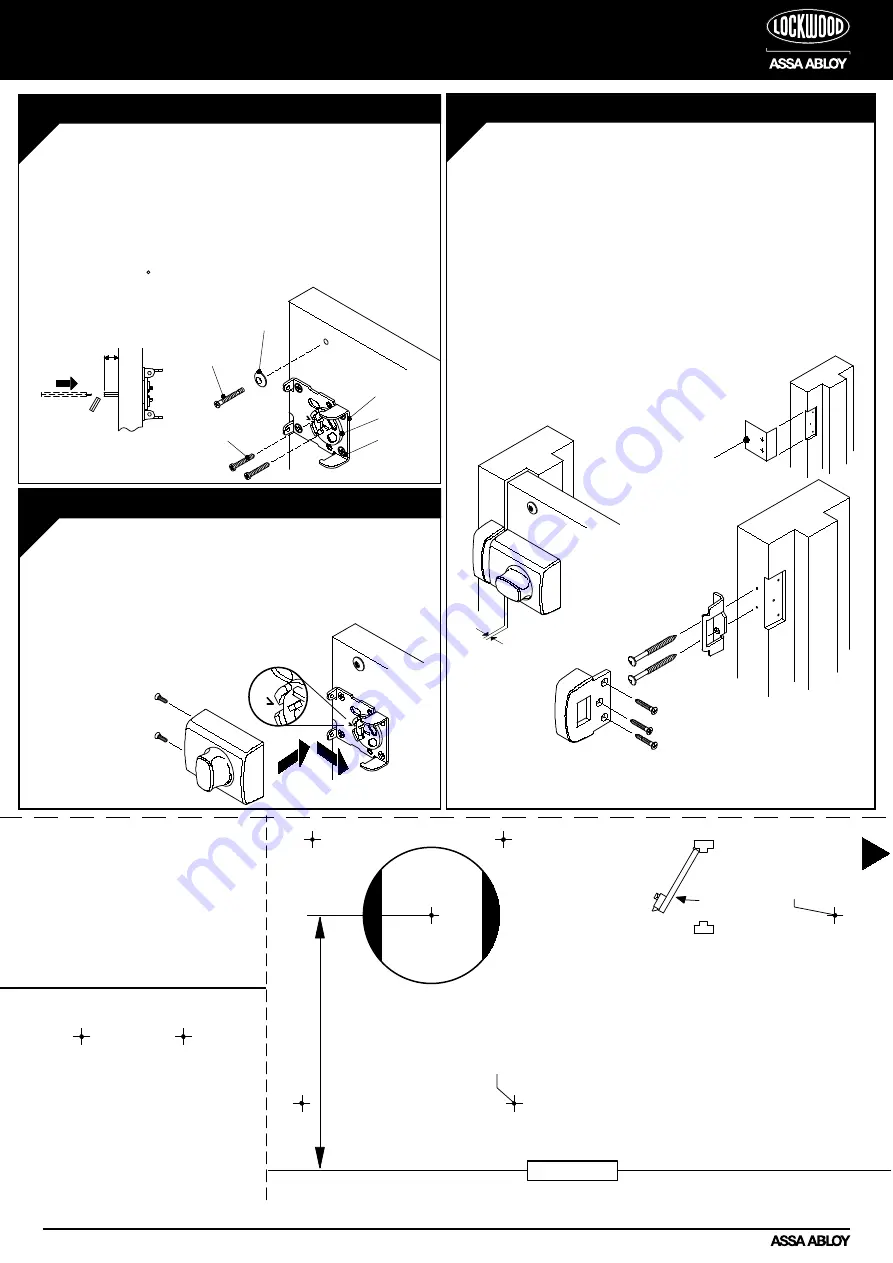
1. Rotate lever fully clockwise to the HOLD BACK position.
2. Ensure notch on hub is aligned with ‘V’ on mounting plate.
Fit case body to mounting plate as shown.
3. Lightly tap both front corners of case to ensure it is fully
home on the mounting plate.
4. Secure to mounting plate using the two case
mounting screws.
5. Test entire operation of lock
BEFORE CLOSING THE DOOR.
4
INSTALL CASE
Case Mounting
Screws (2)
Mounting Plate
Screws (4)
Digital Lock Mounting
Screws, Flat Head (2)
DOOR
Hub
Mounting Plate
Cup
Washer
Digital Lock
Mounting
Screw
DO NOT OVER TIGHTEN DURING INSTALLATION
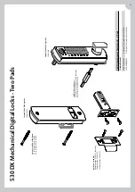
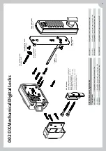
1. Fix MOUNTING PLATE to door with four woodscrews supplied.
2. Align Notch on HUB with vee on mounting plate.
3. Insert and locate, blade end of spindle into hub from outside of door.
Mark and cut spindle to length. (19mm from Door Face).
4. Insert spindle into digital lock drive gear with blade end facing out.
5. Realign notch on hub with vee on mounting plate. Secure digital lock
with mounting screw through cup washer and into top hole.
Cut screw if required. Ensure blade end of spindle engages in hub.
6. Place rear digital lock mounting screw through slot in hub and secure
digital lock to door.
7. Rotate HUB 90 by entering code of Digital Lock and turning knob.
Hold in position and secure second screw.
3
INSTALL DIGITAL LOCK & MTG PLATE
Spindle
19mm
Содержание Lockwood 002 DX
Страница 5: ...DX Mechanical Digital Locks ...
Страница 12: ...Mounting Instructions and Templates ...
Страница 22: ...Notes FOR INFORMATION CALL 1300 LOCK UP 1300 562 587 OR VISIT LOCKWEB COM AU ...
Страница 23: ......


