background image

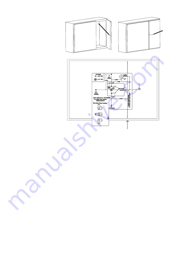
Double Door 

Prepping

1. 

Establish centerline on 

inside of stationary door.

2. 

Continue centerline onto 

outside face of cabinet.

3. 

Align offset line on template 

to the edge of the stationary 

door and align centerline above. 

Remove backing and apply 

template to cabinet face.

4. 

Use punch to mark drilling 

locations, then drill mounting 

holes. If using mechanical 

Key override, drill key 

override hole as well.

Diagram 5: 

Double Door Prep

CTR Line

Offset Line 

& edge of 

stationary 

door

of 12

Содержание HES Aperio K100

Страница 1: ...hreadlock Pillow pack H 2X AA Lithium Batteries AA Lithium Batteries required Use of other types of batteries such as Alkaline will significantly decrease battery life Diagram 1 Product Components A D E F G H I Hardware a c b d e f g h i B C I Hardware a 2 56 X 7 16 2x b 8 32 X 5 16 c 6 32 X 5 16 3x d 6 X 1 2 6x e 8 32 X 2 3 4 2x f 8 32 X 1 3 4 2x g 8 32 X 2 1 2 2x h 8 32 X 3 Rod i 8 23 Nut 1 of 1...

Страница 2: ...Orientation C Lock Orientation Options Recommended Tools Flathead Drivers 3 32 3 16 Drill DrillBits 1 16 3 16 1 2 Phillips Drivers PO P2 Pencil Wire Stripper Level Square Ruler Punch Scissors Diagram 2 Orientation Options 2 of 12 ...

Страница 3: ...d 2 1 16 8 32X2 3 4 NoCut Product Specifications Wireless Frequency 2 4GHz IEEE 802 15 4 using AES 128 bit encryption Lock Battery Type AA Lithium 1 5 Volts V Battery Life 50 000 cycles All battery life claims are approximate and based on a set configuration profile Battery performance is based on pre defined system settings such as battery chemistry and battery model used credential presentation ...

Страница 4: ...ine should match with the interior edge of the cabinet wall 4 CONTINUE CENTERLINE to the face of cabinet drawer 5 ALIGN template to offset line and centerline Remove backing an apply template onto cabinet drawer face 6 Usepunch to markdrilling locations thendrill mounting holes Ifusing mechanical Keyoverride drill key overrideholeas well Diagram 3 Installation Template Strike Plate Template Diagra...

Страница 5: ...fset line on template to the edge of the stationary door and align centerline above Remove backing and apply template to cabinet face 4 Usepunch to markdrilling locations thendrill mounting holes Ifusing mechanical Keyoverride drill key overrideholeas well Diagram 5 Double Door Prep CTR Line Offset Line edge of stationary door 5 of 12 ...

Страница 6: ...IGN reader with mounting holes and pull cable through as shown Trim the threaded rod to length as outlined in Mounting Screw Length table on page 3 2 ADD Threadlock to threaded rod Secure Reader to cabinet drawer using the cut threaded rod and coupling nut DO NOT over tighten Diagram 6 Reader Installation Diagram 7 Installing Batteries 6 of 12 ...

Страница 7: ...ace using 2x screw f and 2x screw d DO NOT over tighten If required use Screw e or g instead of f 3 PLUG cable into slot on lock body 4 Tuck excess cable into lock body cavity as shown in Diagram 9 5 For cabinet drawer face thicker than 1 2 add a third Screw d as shown in Diagram 10 Diagram 8 Step 1 2 Diagram 9 Step 3 4 Diagram 10 Step 5 7 of 12 ...

Страница 8: ...INSERT CAM LOCK through the outside of the cabinet drawer face and secure with locking nut 2 INSERT the end of Cam into the mechanical override and secure with nut as shown in Diagram12 OPTIONAL OPTIONAL IMPORTANT NOTE Reader MUST be programmed before installing the strike plate If the cabinet is closed before the reader in programmed and after the strike plate is installed you will be locked out ...

Страница 9: ...en tighten 3 After the strike plate is in the desired position fasten Screw d into strike plate as shown in Diagram 15 Double Door Strike Plate Installation 1 ALIGN double door bracket with mounting holes from the strike plate template 2 Secure strike plate to the double door bracket using 3x Screw d as shown in Diagram 16 Diagram13 Strike Plate Template Use Diagram16 Double Door Strike Plate Inst...

Страница 10: ...lashes Access Control Lock Offline Flashing Yellow UHF Communication Aperio Hub Specifications Approvals CE ETL FCC IC C Tick Safety Emissions FCC 47CFR Part 15 subpart B and subpart C IC RSS 210 EN ETSI 301 489 17 v2 1 1 ENETSI 300 328 v1 7 1 EN 60950 1 ed 2 2007 Dimensions 82mm x 82mm x 37mm Power Supply 8 24 VDC Current 250 mA minimum Internal Antenna 2 cross polarized dipoles External Antenna ...

Страница 11: ... approved access the approval input can be activated by a relay with NO attached to Green LED and C to GND The Red LED input is used to indicate access denied If the RED LED signal is not connected the lock will flash RED three times when a non approved card is presented indicating loss of connection to the hub rather than access denied Any other codes may be reference on the LED reference card Fo...

Страница 12: ...énère utilise et peut émettre des fréquences radio et s il n est pas installé et utilisé conformément ment aux instructions du fabricant peut causer des interferences nuisibles aux communications radio Rien ne garantit cependant que l interférence ne se produira pas dans une installation particulière Si cet équipement provoque des interférences nuisibles à la réception radio ou de télévision qui p...

Отзывы: