8
ED7800 Series
Installation Instructions
Concealed Vertical Rod Exit Devices
FM466 04/20
Copyright © 2018, 2020, ASSA ABLOY Access and Egress Hardware Group, Inc. All rights reserved. Reproduction in whole or in
part without the express written permission of ASSA ABLOY Access and Egress Hardware Group, Inc. is prohibited.
For installation assistance contact Corbin Russwin
1-800-543-3658 • [email protected]
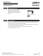
1.
Apply top strike on header with
screws furnished. (Figure 18)
2.
Install bottom strike. (Figure 19)
• If not using threshold, mortise
bottom strike into floor, lining up
carefully with bolt centerline.
• With metal threshold, drill 7/8"
hole in threshold in line with
centerline of bottom bolt.
11
Install Strikes
Top Strike
Door
CL
of Bottom Bolt
(Backset)
Figure 15
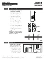
1. Following template furnished, mark
bolt backset on outside of door.
2. Press in top latch plunger screw to
project top latch and bottom bolt.
3. Put operator in locked position.
4. Center operator on backset line
so top side of lifting lever contacts
underside of auxiliary lifting flange.
(Figure 15)
5. Spot door through hole at top of
operator and drill starting hole with
No. 18 drill for self-tapping screw.
6. Mount operator with screws
furnished.
7. Unlock operator and swing operator
lever to side retracting latch and bolt.
(Figure 16)
8. Spot and drill hole with No. 18 drill
for self-tapping screw.
9. Secure.
NOTE: If door offers too much resistance
to self-tapping screw, use next larger drill.
(See chart, marked Figure 17)
10
Install Outside Operator
Figure 16
Self Tapping
Screws
Size
% Thread
No. 18
75%
11/64"
70%
No. 17
65%
No. 16
55%
Figure 17
Figure 18
Figure 19


