Assa Abloy Corbin Russwin ED5860 Series Скачать руководство пользователя страница 13

13

ED5860 (B) Series

Installation Instructions

Exit Device

FM544  02/20

For installation assistance contact Corbin Russwin 

1-800-543-3658 • [email protected]

Copyright © 1998, 2020 ASSA ABLOY Access and Egress Hardware Group, Inc. All rights reserved. Reproduction in whole 

or in part without the express written permission of ASSA ABLOY Access and Egress Hardware Group, Inc. is prohibited.

Installation (continued)

Complete Installation (continued)

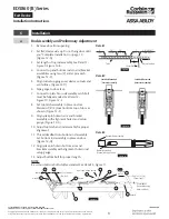
e.   Adjust bottom rod with adjusting screw 

C2. (Figure 21)

f.   With top latch retracted in hold back 

position, and touchbar dogged or fully 

depressed, adjust bottom rod so that 

deadbolt clears strike by 1/16

"

 (1.6 mm). 

The bottom rod should be in position in 

active case with square head of connector 

hanging in the guide. 

g.   Check device operation by opening 

and 

closing the door. An additional minor 

adjustment may be required for full 

retraction and correct strike engagement. 

Top latch should consistently go into 

holdback with gentle (full) press of 

touchbar.

Note: 

To avoid thread damage and 

provide 

positive locking, be sure set screws engage 

flats on adjusting screws.

5.   After acceptable device function, install 

third 

screw in top strike to lock strike in position 

with 10-24 x 3/4" PFHMS.

6.   Install device cover and end cap with (2) 

8-32 

PFHMS each.

Figure 21 


C2

Cover 

Screw 

Hole

3/8

(10)

Bolt  

Engagement

Bottom Adjusting Screw

Longer (CW)

Shorter (CCW)
Bottom Rod

Содержание Corbin Russwin ED5860 Series

Страница 1: ...nd Egress Hardware Group Inc is prohibited FM544 02 20 For installation assistance contact Corbin Russwin 1 800 543 3658 techsupport corbinrusswin assaabloy com WARNING This product can expose you to...

Страница 2: ...ithout the express written permission of ASSA ABLOY Access and Egress Hardware Group Inc is prohibited TOC Table of Contents 1 Package Contents 3 2 Options 4 3 Dogging 4 4 Plastic Installation Templat...

Страница 3: ...Hardware Group Inc is prohibited 1 Package Contents Top Strike Top Latch Top Tube 5 Cotter Pin 8 2 44m Opening 7 6 2 29m Opening 7 2 2 18m Opening 7 2 13m Opening Top Rod 2 Arm and Bracket Assembly 2...

Страница 4: ...oup Inc is prohibited 2 Options 1 4 20 Sex Nut Option Standard for Fire Rated doors Recommended for wood and unreinforced metal doors Device Quantity Size All No Trim 4 1 4 20 All With Trim 2 Rod Exte...

Страница 5: ...llation Template For use in conjunction with instruction sheets packed with exit device Holes and slots are identified below by exit device series and trim Prep door and frame for only those features...

Страница 6: ...ith walls having a structural thickness metal skin plus reinforcement to engage less than three 3 full screw threads are considered unreinforced Unreinforced Doors Use SNB sex nuts and bolts or Blind...

Страница 7: ...ark Door Single Door or Pair without Mullion Locate and mark horizontal and vertical centerlines as shown Figure 6 LHR door shown Preparation is typical for both door hands Figure 6 Caution If device...

Страница 8: ...s and frames with factory made cutouts are recommended 5 Locate and tape trim template to door See instructions packed with trim 6 Mark and prepare holes per installation template Device and Bolt Case...

Страница 9: ...tended See Detail 2 Figure 10 Figure 12 E 8 Set top latch assembly in place on door Maintain 1 8 3 location from top of door as shown Figure 12 F 9 Align yoke pin holes in arm and bracket assembly wit...

Страница 10: ...two 2 yoke pin assemblies into arm and bracket assemblies Figure 14 E Detail 1 Figure 13 1 4 6 4 Yoke Pin E ring Groove Set Screw 8 32 PHPMS Temporary Screws Figure 14 A E B C c Install Device 1 Moun...

Страница 11: ...production in whole or in part without the express written permission of ASSA ABLOY Access and Egress Hardware Group Inc is prohibited 6 Installation continued d Install Strikes Figure 17 X Y Centerli...

Страница 12: ...nto strike in down position without dragging on floor surface in up position 3 Test device action by touchbar by trim and by dogging Adjust as needed 4 Adjust rod for proper bolt throw a Use 3 32 2 4...

Страница 13: ...d adjust bottom rod so that deadbolt clears strike by 1 16 1 6 mm The bottom rod should be in position in active case with square head of connector hanging in the guide g Check device operation by ope...

Страница 14: ...tten permission of ASSA ABLOY Access and Egress Hardware Group Inc is prohibited 7 Maintenance Periodically remove covers and coat mechanisms with an appropriate lubricant This is particularly essenti...

Страница 15: ...tact Corbin Russwin 1 800 543 3658 techsupport corbinrusswin assaabloy com Copyright 1998 2020 ASSA ABLOY Access and Egress Hardware Group Inc All rights reserved Reproduction in whole or in part with...

Страница 16: ...l rights reserved Reproduction in whole or in part without the express written permission of ASSA ABLOY Access and Egress Hardware Group Inc is prohibited For installation assistance contact Corbin Ru...

Отзывы: