


9
ED5860 (B) Series
Installation Instructions
Exit Device
FM544 02/20
For installation assistance contact Corbin Russwin
1-800-543-3658 • [email protected]
Copyright © 1998, 2020 ASSA ABLOY Access and Egress Hardware Group, Inc. All rights reserved. Reproduction in whole
or in part without the express written permission of ASSA ABLOY Access and Egress Hardware Group, Inc. is prohibited.
6
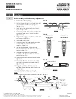
Installation
a
Rod Assembly and Preliminary Adjustment
1. Remove door from opening.
2. Set flat; device side up. Do not hang door until
you
"
on page 12.
3. Set length of top rod assembly. See Detail 1 -
4. Connect top and bottom rods to arm/bracket
assemblies using two (2) cotter pins each.
5. Align rod setup gauge over device cutouts and
centerlines. (Figure 12-D)
6. Tape gauge to door face.
7. Connect top latch to rod assembly. Latchbolt
must be fully extended. See Detail 2 -
8. Set top latch assembly in place on door.
Maintain 1/8" (3) location from top of door as
shown. (Figure 12-F)
9. Align yoke pin holes in arm and bracket
assembly with alignment hole in rod setup
gauge. (Figure 12-G)
10. Adjust top latch and rod assembly for proper
alignment.
11. Thread deadbolt into bottom rod assembly.
Set bottom rod assembly in place on door.
12. Align yoke pin hole in bottom arm and
bracket assembly with alignment hole in rod
setup gauge.
13. Adjust bottom bolt for proper length.
Detail 1
Figure 9
8'
(2.4 M)
7'
(2.13 M)
4
"
(102)
6'8
"
(2.03 M)
(FIELD DRILL)
Adjust Top Rod
Cotter Pin
Tube
7'6
"
(2.29 M)
7'2
"
(2.18 M)
Detail 2
Latchbolt Extended
(Correct Assembly)
Latchbolt Retracted
(Incorrect Assembly)
Figure 10
Detail 3
Bottom Rod Assembly
Bolt fully extended
(Pin toward top of door)
Figure 11
NOTE:
Be certain bottom bolt is fully extended. See Detail 3 - Figure 11.
Yoke Pin
Holes
Centerline of
Device Mounting
Holes and Rods
Gap* + 3/8 (10)
(*From Step 1)
1/8
(3)
(Hold)
Detail 2
Detail 1
4 Free Threads
(Typ. Ref.)
Detail 3
Rod Setup Gauge FM169
Figure 12
F
G
G
D
H
E
G
H
H
H
A
C
B
C


